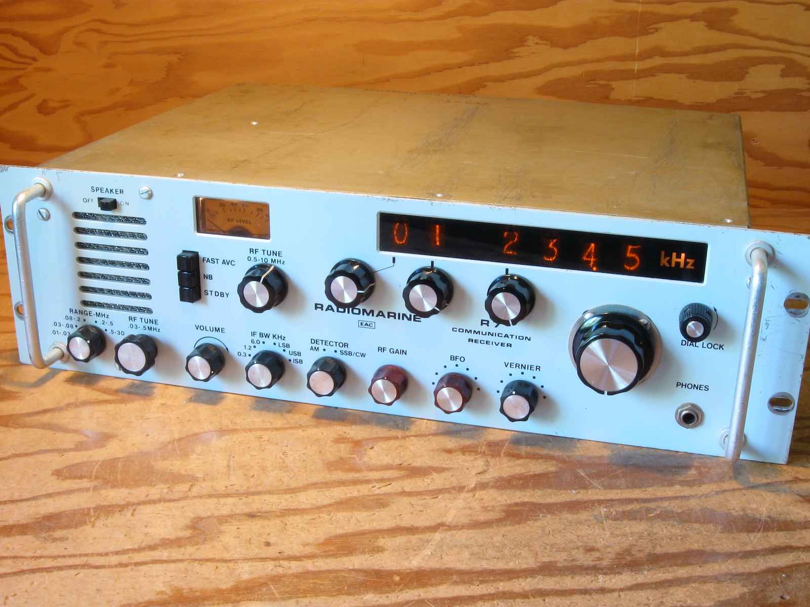
 The Drake MSR-2 is a synthesized-tuning shortwave receiver from the early 1970s.
These receivers were also badged as the Hagenuk EE-334 and EAC/Radiomarine R7, the unit here being an example of the latter.
The Drake MSR-2 is a synthesized-tuning shortwave receiver from the early 1970s.
These receivers were also badged as the Hagenuk EE-334 and EAC/Radiomarine R7, the unit here being an example of the latter.
| bh | Drake MSR-2 Shortwave Receiver |
The Drake MSR-2 is a synthesized-tuning shortwave receiver from the early 1970s.
These receivers were also badged as the Hagenuk EE-334 and EAC/Radiomarine R7, the unit here being an example of the latter.
The tuning system is a modified Phase-Locked-Loop scheme, described below. Drake used a similar tuning scheme in their TR-7 amateur transceivers.
| CONTENTS (this page): | SUB-PAGES: |
| RELATED: | EXTERNAL LINKS & REFERENCES: |
 As a user, one tunes the DSR-2 via 3 multi-position switches to select the tens-MHz, units-MHz, and hundreds-KHz digits of the frequency, while the 100KHz span of the lower digits (displayed as tens-KHz, units-KHz, and hundreds-Hz) are tuned via a continuous-turn knob.
The tuned frequency as seen in the NIXIE display is thus composed as:
As a user, one tunes the DSR-2 via 3 multi-position switches to select the tens-MHz, units-MHz, and hundreds-KHz digits of the frequency, while the 100KHz span of the lower digits (displayed as tens-KHz, units-KHz, and hundreds-Hz) are tuned via a continuous-turn knob.
The tuned frequency as seen in the NIXIE display is thus composed as:
	ss,scc.c KHz
where
	s = switch
	c = continuous
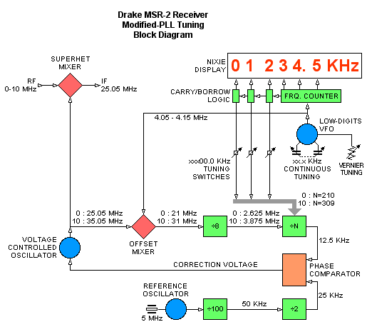
The diagram to the right shows a simplified block diagram of the tuning system, with some values shown for the 0 to 10 MHz reception spectrum (higher frequencies use some different ranges of values). The system is a Phase-Locked-Loop scheme, but the standard PLL organisation is modified by the addition of a mixer between the VCO and phase detector.
The 3 multi-position switches determine the loop division factor (÷N). The continuous-turn knob tunes a variable-capacitor-tuned VFO across a 100KHz span. The output of this 'low-digits' VFO is injected into the PLL via the offset mixer, introducing an error-offset frequency into the loop, to the effect that the phase detector will correct the VCO - and hence the tuned frequency - to include the offset. The 'Vernier' knob tweaks the frequency of the low-digits VFO across a few hundred Hz. The low-digits VFO is itself outside the PLL error-correction loop, any drift in this VFO will affect the tuned frequency, so it must be an adequately stable design.
For the 0 to 10 MHz region, the basic loop equation for the received frequency is:
	R = 12.5*8*(210+H) + (4050+L) - 25,050 KHz
where
	R = received frequency
	H = integer in 0 .. 99 (upper digits)
	L = continuous 0 .. 100 (lower digits)
The low-digits VFO incorporates a wrap-around feature allowing one, for example, to tune 1200 thru 1300 KHz and wrap around back to 1200. This is implemented as dual oscillators controlled by a dual variable capacitor with vanes arranged 180 degrees out of phase such that one set of vanes is opening as the other set is closing. A mechanical switch on the same shaft selects which vanes and oscillator are active.
A related feature is the allowance of a few KHz of extension or overlap at either end of the 100 KHz span so one can continuously tune in the vicinity of (for example) 1200 KHz without having to rotate the upper-digit switches. This necessitates some logic to perform carry and borrow functions into the upper-digit displays as the frequency counter for the lower-digits overflows and underflows the basic 100 KHz span.
The tuning one actually sees then, over the 1200 to 1300 KHz span, will be something like:
	1200.0 -- 1250.0 -- 1300.0 -- 1303.7  12bb.b  1197.4 -- 1200.0 -- etc.
where
	b = blanked
The 12bb.b is displayed during the wrap-around, the limit frequencies at the wrap-around may vary due to the vagaries of the mechanical switch doing the dual-VFO switchover.
The digital portion of the tuning system is implemented with 7400-series SSI/MSI ICs.
 Top view of interior. |
 Top view with covers removed. |
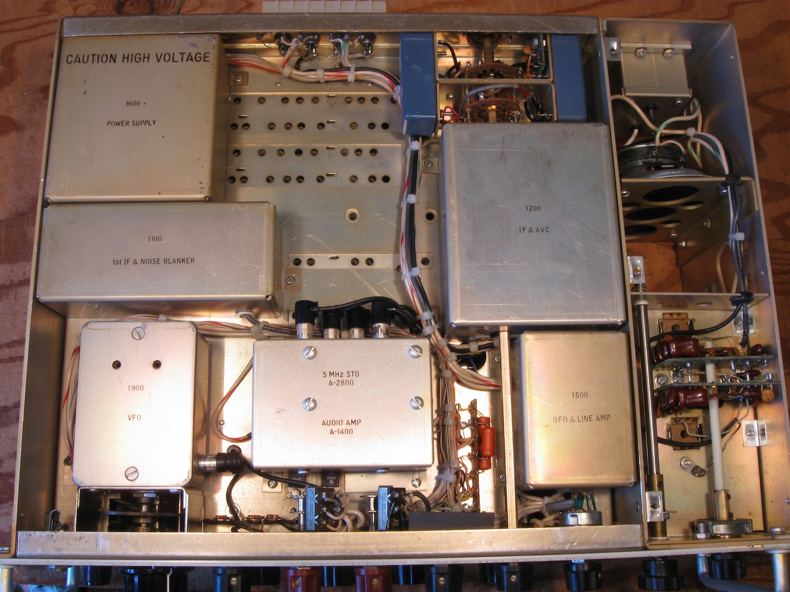 Bottom view of interior. |
 Bottom view, covers removed. |
 Counter and Display boards, component side. |
 Counter and Display boards, solder side. |
 Problematic wire connectors. These generally need to be soldered over for reliability. |
|
Unit Log
Drake MSR-2 |
bhilpert 2016 Feb |