The Service ROM Card is a new (2024) plug-in ROM card providing two functions:
- Boot-program options to assist with servicing.
- Programmable option-ROM card.
The 9830 relies on a lot of logic to merely boot.
The microcode engine, the microcode ROM, RAM, the firmware Basic ROM, IO logic, etc.,
must all be functioning to some level just to get the lazy-T to appear on the display.
In a situation where the machine fails to boot, the Service ROM can help to delineate and isolate the level at which the failure is occurring.
The Service ROM provides several small switch-selected programs for the machine to execute at boot, instead of executing the Basic ROM.
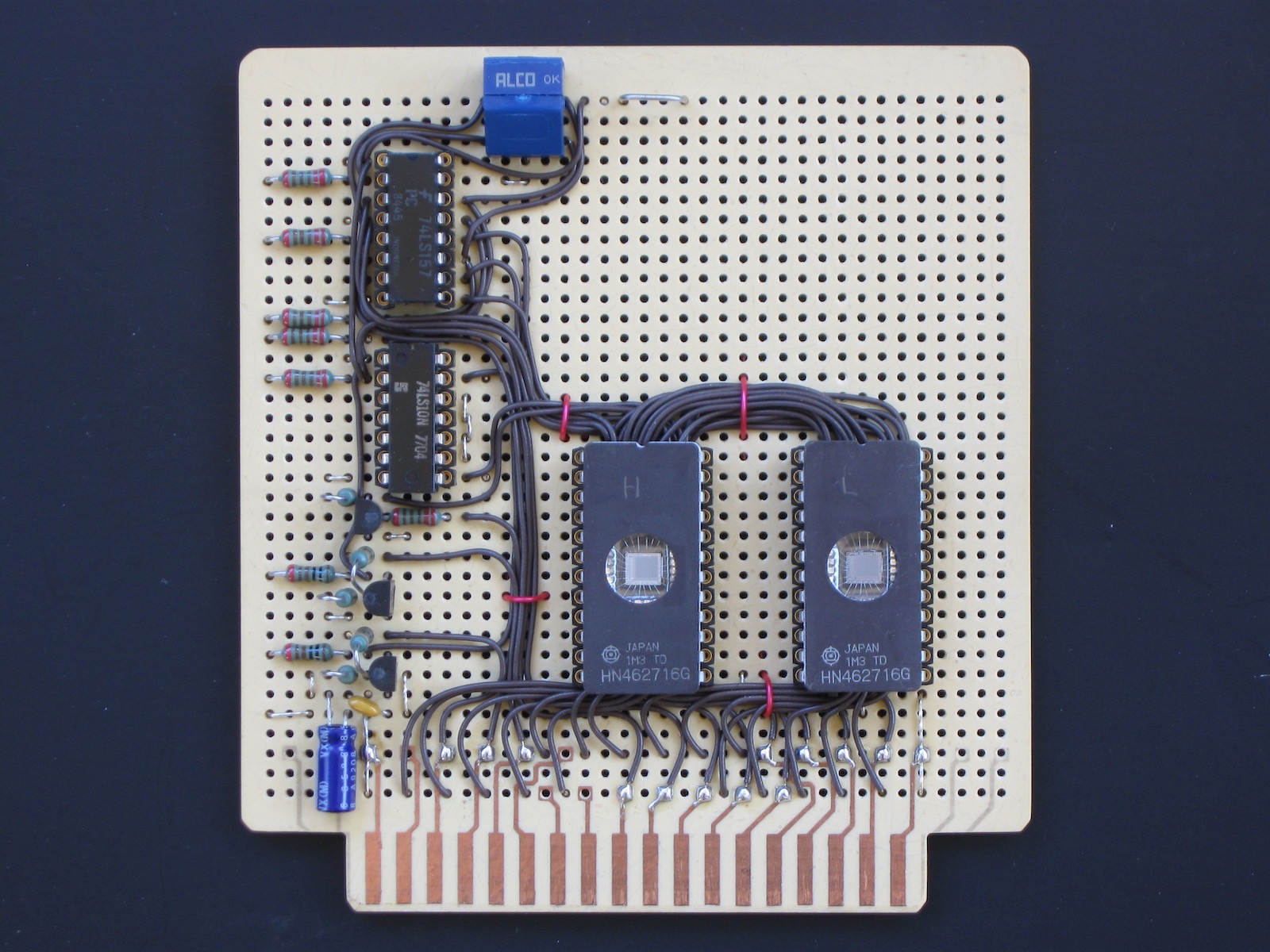
The Service ROM is a ROM card to be plugged into one of the internal option-ROM card slots of the 9830.
It uses two 2716 EPROMs, one for the high-order bytes of words and one for the low-order bytes.
1K of the 2KWords provided by the 2716s functions as the page of an option-ROM.
Any desired firmware extensions could be programmed into this 1K page, a suggested use is for the Machine Binary Block.
The other 1K of the 2716s serves as 16 64-word boot segments where each segment is a small boot program.
Which segment is executed at boot is selected by 4 switches.
The switches select a 64-word span of locations in the ROM to be re-mapped to appear at addresses 0 to 63 in the 9830 address space.
|
Contents (this page):
|
Resources:
|
Operation
At boot time or upon reset, the processor starts execution at location 0.
Normally this is, of course, the firmware Basic ROM.
To use the Service ROM, the nROMB00 signal (ROM Bank 0, which encompasses location 0) is redirected to the Service ROM board.
This redirection is accomplished by either:
- Pulling the Basic ROM card and jumpering from the nROMB00 line on the edge connector to the Service ROM, or,
- Mounting the Basic ROM card on extenders, opening the nROMB00 line on the extender and then jumpering to the Service ROM.
Boot Programs
The boot programs for servicing (2024 Jun):
- Jump-to-self Loop: Address 0 contains simply a "JMP 0" instruction.
.
- Read & Write RAM (Stack):
A loop which repeatedly writes a bit pattern to the Stack Pointer location (01777) in RAM and reads it.
- Read & Write RAM:
A loop which repeatedly reads and writes to a location on both RAM boards.
- Sputnik (Beep Loop):
A loop which repeatedly triggers the 9830 beep speaker and delays ~ 1S.
- (defunct).
- Dump Memory:
Prints the memory contents of the entire address space to the printer (select code 15).
Intended to be used with the MPSI functioning as the printer for data capture.
With the Basic ROM board mounted on extenders this can be used to check whether the Basic ROMs have become corrupted.
This program relies on the dump-memory code in the Machine Binary Block, thus the MBB must be in the option-ROM portion of the EPROMS, and the Service ROM Card must be in Card Slot d (slot nearest the front).
Slot d is requred so as to place the dump-memory code at a known target address for a jump from the boot code.
Use as an Option-ROM & Programming the EPROMs
The design can be used as a template for the construction of an arbitrary option-ROM card.
In programming the EPROMs for either boot programs or an option-ROM, note:
- The addressing sequence must be reversed as the negative-logic address bus drives the EPROM address lines.
See the schematic for the EPROM address map.
- The data must be inverted as the EPROMs directly drive the negative-logic data bus.
Other Servicing Notes
- Pull memory boards: If all memory boards (both RAM and ROM) are removed, the data-bus lines float HIGH.
Being negative-logic lines, the processor then sees any memory-reads as all bits 0.
As an instruction, all-0s is "ADA 0" - Add memory location 0 to register A.
The processor should thus traverse through the entire address space, looping back to 0 at the end, performing two memory reads for every instruction: a fetch at the address indicated by the incrementing PC, and a read at location 0.