
| HP 9830 | MPSI Multi-Purpose Serial I/O Interface |
The MPSI is a new (2014) plug-in I/O interface for the HP-9830 that provides for input and output to an external computer (referred to here as the host) over a simple clocked serial line. The MPSI implements 3 devices - that is, it responds to 3 select-codes from the 9830 - in one plug-in module:
The data link between the MPSI and the host is a straight-forward clocked serial line, similar to an SIO interface, involving 5 wires including ground, at TTL or 3.3V signal levels. It is not RS-232 async, the DB-25 connector visible in the photo was used merely because such connectors are abundant in surplus today. The design intention was to keep the hardware requirements (cabling, buffers, signals) to a minimum. The link is expected to be quite short, it is not intended as a medium or long distance communication link.
| Contents (this page): | Resources: |
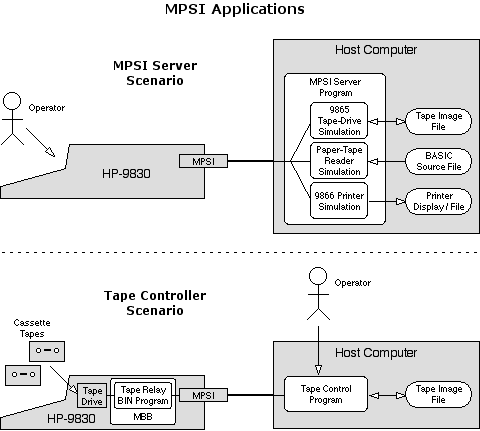
The relay program is a binary program contained in the Machine Binary-Block, and can be downloaded into the 9830 from the host using the MPSI Server program.
Both programs are written in C. See the Resource links above.

The paper tape and printing functions should function down to very slow clocking rates. The General-Mode I/O protocol HP used for these functions is fully ack'd and there are no response latency limitations. Python server programs are adequate here.
The tape-drive functions need clocking of the MPSI in the 1 MHz range and response latency in the tens-of-uS range.
The RPi has been competent for the task even when manipulating the GPIO pins from C code running in userland, as long as there aren't any other tasks distracting the CPU/OS.


The second unit was built on a proto-board with edge connector. The board was trimmed to fit into an original HP interface housing. In this instance the ICs face down, just as they do in original HP interfaces.
See the schematic (PDF).
| 0 | DI0 | bus Data-Input-0 |
| 1 | DI1 | bus Data-Input-1. |
| 2 | DI2 | bus Data-Input-2. |
| 3 | DI3 | bus Data-Input-3. |
| 4 | DI4 | bus Data-Input-4. |
| 5 | DI5 | bus Data-Input-5. |
| 6 | DI6 | bus Data-Input-6. |
| 7 | DI7 | bus Data-Input-7. |
| 8 | - | not used, see ACK bit. |
| 9 | SI1 | bus Status-Input-1. |
| 10 | SI2 | bus Status-Input-2. |
| 11 | SI3 | bus Status-Input-3. |
| 12 | - | not used. |
| 13 | ACK | General-Mode ACK flag, will determine Status-Input-0 on +edge of CTL. |
| 14 | CFI | CFI (Channel-Flag-Input) flag, will determine bus CFI on +edge of CTL. |
| 15 | SSI | SSI (Single-Service-Input) flag, will determine bus SSI on +edge of CTL. |
When CTL=1 the MRR is able to receive requests and output from the 9830. An I/O request from the 9830 asserts the bus CEO (Control-Enable-Output) signal (nCEO=0). When CEO is asserted (-edge of nCEO) the MRR is loaded with the state of the 9830 output bus. When CTL=0 this loading is inhibited. For some Fast-Mode operations which do not require acknowledgement, the MPSI and host may miss an operation from the 9830 if the host does not respond quickly enough to the request from the 9830. Inhibiting the load ensures a subsequent CEO assertion will not corrupt the MRR contents while the host is clocking the MRR.
The +edge of CTL loads the 3 flags in the MPSI (ACK,CFI,SSI) with the corresponding values of MSR bits 13,14,15. The flag flip-flops are present so the other status and data bus inputs from the MSR to the 9830 can be set before indicating their viability to the 9830.
These are LS-TTL inputs to the MPSI with pull-ups and clamps. They are safe for, and can generally be driven by, 3.3V outputs.
| 0 | REQST | Request.
1 indicates the 9830 has initiated an I/O operation on one of the 3 MPSI select-codes.
This is effectively a latched indication of the device-enable signal. This bit returns to 0 after a full 16-bit clocking of the MRR. |
| 1 | TP | Tape-Device. 1 indicates the initiated I/O operation was on the configured TP select-code. |
| 2 | GP | General-Purpose. 1 indicates the initiated I/O operation was on the configured GP select-code. |
| 3 | PR | Printer. 1 indicates the initiated I/O operation was on select-code #15. |
| 4 | nSO3 | inverted bus Status-Output-3. For General-Mode this is the direction bit, 1=output, 0=input. |
| 5 | nSO2 | inverted bus Status-Output-2. |
| 6 | nSO1 | inverted bus Status-Output-1. |
| 7 | nSO0 | inverted bus Status-Output-0. |
| 8 | nDO7 | inverted bus Data-Output-7. |
| 9 | nDO6 | inverted bus Data-Output-6. |
| 10 | nDO5 | inverted bus Data-Output-5. |
| 11 | nDO4 | inverted bus Data-Output-4. |
| 12 | nDO3 | inverted bus Data-Output-3. |
| 13 | nDO2 | inverted bus Data-Output-2. |
| 14 | nDO1 | inverted bus Data-Output-1. |
| 15 | nDO0 | inverted bus Data-Output-0. |
SDI3 is a 3.3V-safe signal.
Typically, the host will monitor the SDI signal, watching for it to be asserted. Because REQST is the first bit in the MRR, its state is normally present on the SDI line. When it is asserted the 9830 has initiated an I/O operation. The host takes CTL low to hold the contents of the MRR and clocks the MRR contents over to the host to obtain the operation data. At the end of the 16-bit clocking, REQST - and hence the SDI line - is deasserted.
Note that the MPSI PR and GP devices both operate in General-Mode, while the TP device uses Fast-Mode.
(!!!NOTE: the gating policy has been implemented to mimic equivalent HP-designed devices. It may be possible to simplify this logic as the firmware may in fact not require some of these mode distinctions.)
|
MPSI
| MBB
| Machine-Language Programs
| HP-9865 Adapter
| Mimic66
Projects HP 9830 |
bhilpert 2014 Feb |