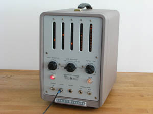
 HP 521C |
 HP 524B |
 HP 524C |
|
 HP 521C |
 HP 524B |
 HP 524C |
| ||||||||||||||||||||||||||||||||||||||||||||||||||||||||||||||||||
Appropriate to the period, these instruments are based on vacuum tube technology, with some use of crystal diodes for triggerring flip-flops and level clamping.
Most of the models of the series utilise the HP AC-4 series of decade counter modules. It may be that the earlier models, such as the 524A, were developed before the AC-4 modules.
The 520 series actually has origins in the HP 520A Nuclear Scaler. This was a 10 MHz 2-decade scaler which would feed into a more typical lower speed counter. The 520A circuitry would be integrated with 6 decades of AC-4 counter modules, a timebase and gate control circuitry to become the 524A.
For the lower frequency models (the 521's and 522B), the base model would count to 120KHz. An option was available to increase this to 220KHz, essentially by replacing the AC-4 counter module in the first decade with the appropriate faster AC-4 module. (Note: the source of data for the table of models did not indicate how the 522B differs from the 521C).
While Hewlett-Packard's first calculators and first computers are sought after by collectors, these instruments were HP's first foray into digital technology.
| Contents (this page): | Sub-pages: | Related pages: |
| The 524 |
| ||||||||||||||||||||||||||
Four versions of the 524 were produced: the A, B, C and D. The 524B superseded the 524A by adding provision for various optional input units to plug into the front panel.
The 524 A and B had a somewhat awkward display in which the 6 most significant digits are neon 1-of-10 columnar displays, while the 2 least significant digits are analog meters marked with 10 positions. Each meter is driven by a staircase signal from a simple resistive D-to-A converter in the according digit's decade counter. The 524 C and D superseded the B by eliminating the analog meters to give a consistent display across all 8 digits. The C and D versions were contemporaries, the D continued the use of columnar displays, while the C went to NIXIE tubes for the display. These versions could also drive a special printer, with the aid of an optional kit.
The 524 versions utilise around 90 vacuum tubes, varying slightly depending on the version.
The physical form factor changed quite a bit from the A to the B to accommodate the front panel plug-in.
The B, C and D are all quite similar physically: a cube of approximately 19-inch rack width (~4 cubic feet),
around 110 to 120 pounds (50 to 55 kg) in weight, and consuming 600 watts of power.
This is what was required in the 1950's to count to just 10 MHz!
| ||||||||||||||||||||
The heterodyne converters do not actually extend the maximum count rate of the counter. Rather, they split the input frequency such that one portion is a known multiple of 10MHz and the remainder is less than 10Mhz. This is accomplished by mixing a selected harmonic multiple of the crystal-controlled 10MHz timebase of the 524 with the input signal to produce a difference signal of less than 10MHz. The appropriate harmonic is tuned-in by the operator. The frequency of the input signal then is computed (manually) as the sum of the harmonic as indicated on the controls (10, 20, 30MHz ...) and the count indicated in the display (0 to 10MHz).
The plug-in input units show up in HP catalogs as late as 1968, but are not present in the 1969 catalog.
Getting the count rate up to 10 MHz was not trivial to accomplish in the tube days, and the 524 presents an example of the limits of using vacuum tubes in the digital mode. The AC-4 decade counter modules are only capable of a maximum count rate of 1.2 MHz. They were thus adequate for the upper 7 digits (MSDs), but not for the units digit (LSD). To get to 10 MHz an exceedingly complex counter for the first decade was required, involving 13 tubes, compared to the 4 tubes for each of the other 7 decades.
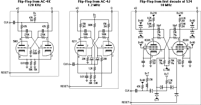
The first issue to be addressed in increasing the count rate is the speed of an individual flip-flop. The 524 used 3 different flip-flop designs for different speeds, as shown in the following diagrams:
|
The low speed flip-flop of the AC-4K module on the left is quite straightforward - note that it uses plate triggering - to count at rates up to 120 KHz.
To improve on this, the flip-flop of the AC-4J moves to grid triggering with the use of diodes, and lower resistances to shorten RC delays. The latter change comes at the expense of increased power consumption of course. A 6211 tube replaces the 5963. These are both 'computer tubes' but the motivation for the change is not clear as the 5963 actually has a higher power rating and lower inter-electrode capacitances. These changes to the counter get the count rate up to 1.2 MHz.
Now look at the flip-flop for the 10 MHz stage:
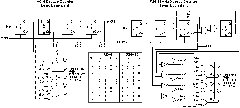
A 4-bit decade counter involves feed-back resulting in additional timing issues when increasing the speed. While the AC-4 modules got by with simply substituting the higher speed flip-flops into the same decade counter configuration, the 10 MHz stage, once again, involves more significant distinctions. The following diagrams show the logic equivalents of these decade counters for comparison:
|
Similar complexities for the higher speed show up around the start-stop gate control circuitry of the 524, as the gate must be precise to within a cycle of the maximum count rate.
| AC-4 Series Decade Counter Modules |
| ||||||||||||||||||||||||||||||||||||||||||||||
The display is either 10 neon bulbs in a column or a NIXIE tube. In both cases the decoding from 4-bit-binary to 1-of-10 is accomplished by placing 10 neon bulbs in the middle of a bi-quinary (2-by-5) matrix. The 3-bit to 1-of-5 decoding is accomplished with resistors. For the 1-of-10 columnar display the 10 neons are then the display.
For the NIXIE display, the common anode of a NIXIE tube meant it was not possible to simply substitute the NIXIE tube for the neon bulbs in the matrix (bi-quinary NIXIEs would come later). Consequently the NIXIE tube display is accomplished by illuminating 10 CdS photoconductors in 1-to-1 correspondance with the 10 neon bulbs, the photoconductors then controlling the 10 cathodes of the NIXIE. This use of photoconductors would be leveraged in a more complex manner by HP in their 1960s-era discrete-transistor decade counter modules.
Low-speed models of the module count to 120 KHz, medium speed models to 220 KHz, and high-speed models - benefitting from reduced resistor values (shorter RC time constants) and diode triggerring - count to 1.2 MHz.
Various models were superseded over the years, e.g. the 4A by the 4G. Differences seem to be the plug type and some capacitor values. The D, F, and H models may have existed but I have no data about them.
Northeastern Engineering Inc. also manufactured some modules almost identical to the AC-4 series. Physically, there are some minor variations in dimensions and the NE models have side panels covering the circuit board. Electrically, the circuit for NE models 140-40A and 140-100C is identical to that of the HP AC-4A, but with slightly different component values, and the NE models do not include the staircase resistors.
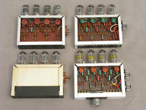
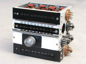
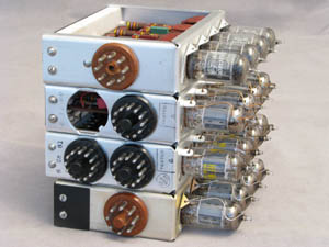
The photos below show three AC-4 models - an AC-4A from 1956, an AC-4G from 1960, AC-4J with NIXIE tube from 1961 - along with a Northeastern 140-100C.
 |
 |
 |
 |
| References, Externals Links |
|
HP 520 Counter Series
Early Digital Test Equipment |
bhilpert Jul 2005 |