|
|

|
Information for this unit was supplied by Jean Campioni in Belgium. Jean's unit was not functioning. Starting with the Canon 161 schematic and after performing some more reverse engineering of portions of the 130S, Jean traced the faults to some bad Ge diodes and was successful in repairing the unit to full function.
The 130S is essentially a repackaging of the Canon 130.
The printed circuit boards and mechanical design were redone.
Notably the displays are mounted on the circuit boards in the 130S,
avoiding the large bundle of wires from the boards to displays present in the 130.

Internal view. Jean also put up a youtube video of the work. |
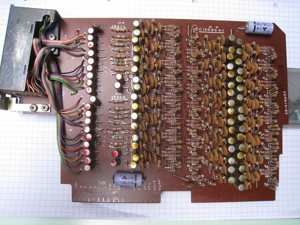
This is one of the 13 boards in the 130S. The circuitry encompasses 8 flip-flops (2 digits) of the IR (indicating register) which feed two 1-of-10 decoder/drivers for the two digit-display modules mounted on the board, and 16 flip-flops (4 digits) of the ACC (accumulator register). |

Solder side of the above board. |

Jean constructed a CMU (Controller/Monitor Unit) to assist in debugging the 130S, using the design for the Canon 161 CMU. The test connector in the 130S is nearly identical to that in the 161. Jean also used IC buffers for the LED drivers instead of discrete transistors. |

An example of the manual markup Jean did on a scan of the board during reverse-engineering. |

One of the control boards mounted on an extender for service. |

And, as often has to be done for machines such as this, extender cards tailored to the machine need to be constructed. |
| 862091 | |
| ? (?) | |
| 2014 Feb | |
| Information only, provided by J.C. All repairs by J.C. |
|
Canon 130S
Calculators | Integrated Circuits | Displays | Simulations EEC |
bhilpert |