|
|

|
A slightly enhanced version of the Canon 130: 16 digits instead of 13, and an additional accumulating memory.
The 161 and 130 are unusual for their period in that they implement a full floating decimal point in which both operands for an operation may be shifted up or down to bring them into alignment. There is no switch to set the decimal point position, in contrast to most electronic calculators of this era. While a considerable amount of logic and complexity is dedicated to achieving this facility, it is nonetheless rather lack-lustre in its thoroughness, leading to some odd and confoundingly erratic behaviour.
| Anomalies: |
|
| Notes: |
|
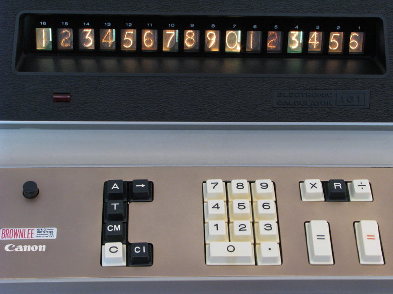
Closer view of the keyboard and display. Note this unit does not have the "M+" and M-" keys, contrast with the 161 at Rick Bensene's site. |
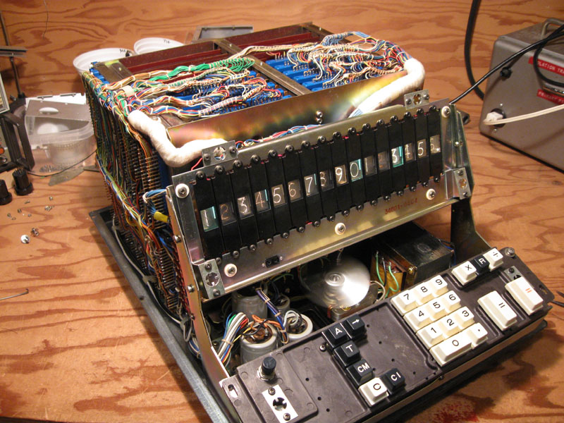
Cover removed. The logic is contained on 11 circuit boards plugged into a hand-wired backplane on the left side. The connectors on top and the large white bundles of wire are the connections to the display. The display is not multiplexed, as a consequence there are over 190 wires connecting the 16 digits of the display. The power supply is below the keyboard. |

Side view showing the backplane wiring and the CMU (Controller/Monitor Unit) attached. The CMU plugs into an extra card edge-connector provided on the calculator. A toggle switch below the connector switches control of the clock over to the CMU. |
|

Board 33, one of the 11 circuit boards containing the calculator logic. The 11 boards are identified as 30 thru 40 in the last two digits of the part number, seen here in the lower left corner of the board. The boards are sequenced front to back when inserted in the backplane. This board contains:
|

Board 33 accessed for service with a home-built card extender. |

View from the rear of board 33 under service. The two test clips are probe leads from the CMU, clipped onto flip-flops in the ME register. |
|
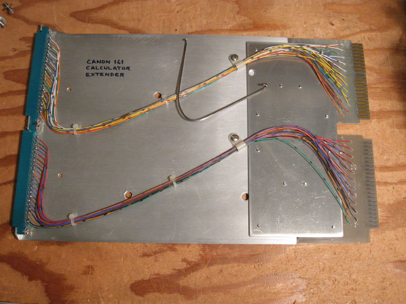
This board extender was constructed from some sheet aluminum, two edge-connector receptacles and the edge-connector fingers cut from two scrap circuit boards. |

A closer view of the CMU. The CMU displays various internal state registers of the calculator, and provides manual control over the clock. The clock can be slowed down at a variable rate, single-stepped, or stop on the processing of each digit or each number/state cycle. Also provided are two binary probes to monitor arbitrary points in the calculator via clip-on test leads. |
| 700369 | |
| 1966 (variable resistors in power supply stamped with 6604, transistors stamped with 6E.) | |
| Power Supply Board labeled with "1964.7 H.SATO" in copper foil. | |
| 08 Dec 2000 | |
| Brownlee Office Equipment. See source note for Canon 130. | |
| Good physical condition. Multiple and inconsistent functional problems: pressing the clear key does not clear all digits; pressing a numeral or operation key results in random numerals in the display and may turn on the overflow lamp. Internal test-mode switch seized. | |
| Fully functional (22 Jan 2001). |
| 09 Dec 2000 | |
| Broken internal test-mode switch replaced. Unit disassembled for cleaning. |
| Jan 2001 | |
| Extender Card constructed to assist in repairs. |
| 07 Jan 2001 | |
| Original power connector replaced with IEC standard. |
| 07 Jan 2001 | |
| Pressing Clear key results in a display of "000000004NNNNNNN" where N = (7 and 9 digits on simultaneously). | |
| The 7-and-9 display results from a value of 15 in a digit register. The symptoms suggest a stuck-high flip-flop in the 4 bit of digit 8. The not-Q, or "0", transistor in the flip-flop, while it would switch (had gain), would not hold the state. | |
| 2SB329 transistor IR15-4-0 replaced with 2N3906 (board 34). |
| 07 Jan 2001 | |
| A slipped test lead resulted in brief application of positive potential to the SP-I line. The display was now completely static with random digits. | |
| Output buffer transistor for SP-I had developed a CE short. | |
| 2SD77 transistor replaced with 2N3904 (board 32). |
| 09 Jan 2001 | |
| Multiple symptoms which all turned out to have a common source: the multiply-bar randomly chooses to increment or remain at digit 1 during digit entry; the decimal point does not move with digit entry; multiply operations ignore all digits of the second operand except for the first, i.e.: 2*123=200; divide results in an infinite loop. | |
| Focusing on the multiply-bar problem: The signal on the R input to flip-flop DC1 was not as expected. Possible intermittent problem with base of transistor. Transistors in DC1 replaced. No improvement. Trigger capacitor substituted. No improvement. Finally FD was observed to be alternating with CP but at a random phase relationship to P-8. RFD is always logic-1. Conjecture that FD should not be alternating at all. If so RFD should not be logic-1. Logic-1 traced back to shorted transistor in buffer for RPABD. The random aspect of the problem resulted from the alternating of FD which presented a 50/50 probability of FD being in the 'correct' state when a key was pressed. | |
| 2SB329 transistor in buffer for RPABD replaced with 2N3906 (board 36). |
| 10 Jan 2001 | |
Lamp repairs:
|
| Jan 2001 | |
| Controller/Monitor Unit designed and constructed to assist in solution of next problem. |
| 22 Jan 2001 | |
| Arithmetic operations intermittently result in random digits in the display. | |
| Schematic analysed to determine data flow during addition. Bad data then observed to be emerging from ME register during CC6. Source of bad data traced to flip-flop ME14-2. The flip-flop sometimes sticks high. The not-Q, or "0" transistor would not always stay off. Observation of base and collector signals with a scope suggests a leaky BC junction. Essentially the same problem as that of the incomplete-Clear repair of 07 Jan 2001. | |
| 2SB328 transistor ME14-2-0 replaced with 2N3906 (board 33). |
| 22 Jan 2001 | |
| Numeral 7 of digit 14 does not light. Lamp is not burned out. | |
| Associated driver transistor found to have open BE junction. | |
| 2SB77 transistor replaced with 2N3906 (board 33). Unit now restored to full functionality. |
| 07 Nov 2010 | |
| Arithmetic operations result in both 7 & 9 illuminated throughout the display (display for digit value 15). | |
| CMU used to follow state transitions and trace data flow during add. Transitions are (2->)3->6->7, 2 only occurring if decimal points have been entered. 3:IR->ACC, 6:ACC->ME. Data is lost in ME. Traced to transistor ME15-1-0, will not turn on, base remains slightly negative even when C of opposing transistor is shorted to ground. | |
| 2SB328 transistor ME15-1-0 replaced with 2N3906 (board 33). |
| 07 Nov 2010 | |
| Briefly after above repair; hitting "=" key with value in display erratically results in various digits being cleared, 111*111->12221, other arithmetic errors. | |
| Traced to transistor ME14-1-1, will not turn on, behaviour just like ME15-1-0. | |
| 2SB328 transistor ME14-1-1 replaced with 2N3906 (board 33). |
| 17 Nov 2010 | |
| CMU improved with Step-Digit and Interval functions. Bounce on new controls is a little odd. With 0.01 cap on switches, there is an action on both push and release of switch. With no cap, there is an occasional double-pulse, but tolerable. Jumpers to two caps cut to take them out-of-circuit. |
| 17 Nov 2010 | |
| Unused connector pin NTL connected to -10V on calculator to supply power to the CMU, to avoid the extra clip lead from the CMU. |
| 12 Nov 2021 | |
| An entered number disappears after A or S keys are pressed (IR is cleared). | |
| IR data enters Sum/ACC in CC3 but ACC12-1 is stuck high. Reverted to working, intermittent, failure not found. |
| 13 Nov 2021 | |
| Edge connector on extender board broken while attempting to insert board 37. Both edge connectors replaced. Extender lengthened and notch cut in lower edge so it can be angled into slot. |
| 13 Nov 2021 | |
| Load resistor for gate 36A46 broken while attempting to insert extender. 12K replaced with 14.3K. |
| 14 Nov 2021 | |
| Fuse for -10V blew while powered up. | |
| Boards removed and inserted one-by-one with ammeter in -10V circuit, measurements taken. No shorts or excessive current observed. Perhaps a mechanical short from movement of board 40 into rear of card cage. | |
| -10V fuse (3A) replaced with 3A from +10V. +10V replaced with 2.5A. |
| 15 Nov 2021 | |
| Digit 8 bit 1 changes to 0 a moment after an entry or result, e.g. 3 changes to 2, 7 to 6. | |
| Reverted to working, intermittent, failure not found. |
| 21 Dec 2021 | |
| Transistor IR8-4-0 has been replaced with 2N3906, but no log record was made. |
| 21 Dec 2021 | |
| Displayed digit 8 bit 2 changes to 0 a moment after an entry or result, e.g. 3 changes to 1, 7 to 5. Fault is temperature-dependant. OK with ambient <15C, bad at >15C. Observation of 15 Nov was probably incorrectly recorded regarding the bit at fault. | |
| MM measurements do not show out-of-range differences for either transistor of IR8-2. Fault is probably BC leakage in IR8-2-1. | |
| 2SB328 transistor IR8-2-1 replaced with 2N3906 (board 32). |
| 12 Jan 2022 | |
| Version 3 of CMU implemented.
FM LED does not go fully off. nFM=1 measured as -8.63V. Not clear why this isn't closer to -10, suggests CE leakage. Pull-down R on NPN LED driver added to get LED off. |
| 14 Jan 2022 | |
| Number entry is OK but operation results can be erratic, with 1 bits transformed to 0, e.g. 7 to 5. | |
| Number of digits tends to remain correct, suggesting problem may occur in transfers between registers in totalising sequence. Loss of bits is far worse when single-stepping with CMU. CMU used to isolate fault through binary reduction: data into ME in CC6 OK - thus not ACC; at ME9-1 not OK; at ME13-1 not OK; at ME14-8 not OK; at ME16-1 not OK; at ME16-2 not OK; ME16-1 can be seen toggling to 1 state but will not hold that state, reverting to 0. BC of ME16-8-1 measures bad once removed but new transistor does not resolve problem. More tracing leads to ME13-2-1. | |
| 2SB328 transistor ME16-8-1 replaced with 2N3906 (board 33).
2SB328 transistor ME13-2-1 replaced with 2N3906 (board 33). |
| 23 Jan 2022 | |
| Number entry is OK but operation results can be erratic, with 0 bits transformed to 1. Results are always incorrect when single-stepping with CMU. | |
| CMU used to isolate fault through binary reduction: traced to FF ACC2-2 sticking 1. | |
| 2SB328 transistor ACC2-2-0 replaced with 2N3906 (board 40). |
| 05 Feb 2022 | |
| After being on for awhile, Total key presents extra 1 bits appearing in upper digits of ME. More bits above the initial fault digit are set 1 on each Get-Total. | |
| Selective single-bit number entries indicate ME14-1 is sticking 1 for awhile while being clocked. | |
| 2SB328 transistor ME14-1-0 replaced with 2N3906 (board 33). |
| 05 Oct 2025 | |
| Addition or Recall results in garbage display, even immediately after Clear-all. | |
| Traced with CMU to board 40, then with grounding of ACC FF collectors to ACC5-4 sticking 1. CE leaky. | |
| 2SB328 transistor ACC5-4-0 replaced with 2N3906 (board 40). |
|
Canon 161
Calculators | Integrated Circuits | Displays | Simulations EEC |
bhilpert |