|
|

|
An unusual feature of the model is lamps in the multiply and divide keys which illuminate to indicate the according operation is pending. While a curious feature in itself, it is actually part of the provision of a 'constant' feature. The lamps remain lit after the completion of the operation, and another multiply or divide can be performed with the earlier second operand. Pressing the += key a second time after completion of an operation clears the constant state, indicated by the lamp turning off.
A cute internal technical aspect of this model is a two-speed clock. The master clock is an astable flip-flop, but with - so to speak - two flip sides and one flop side, with different timing components connecting the two flip sides to the flop side. The slower flip side is enabled for idle display, while the faster flip side is enabled during calculation.
| Anomalies: |
|
| Notes: |
|
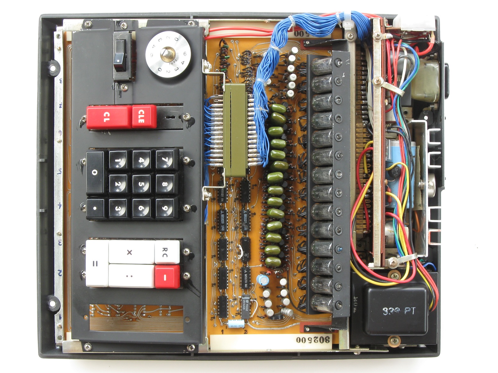
Top of case removed. |
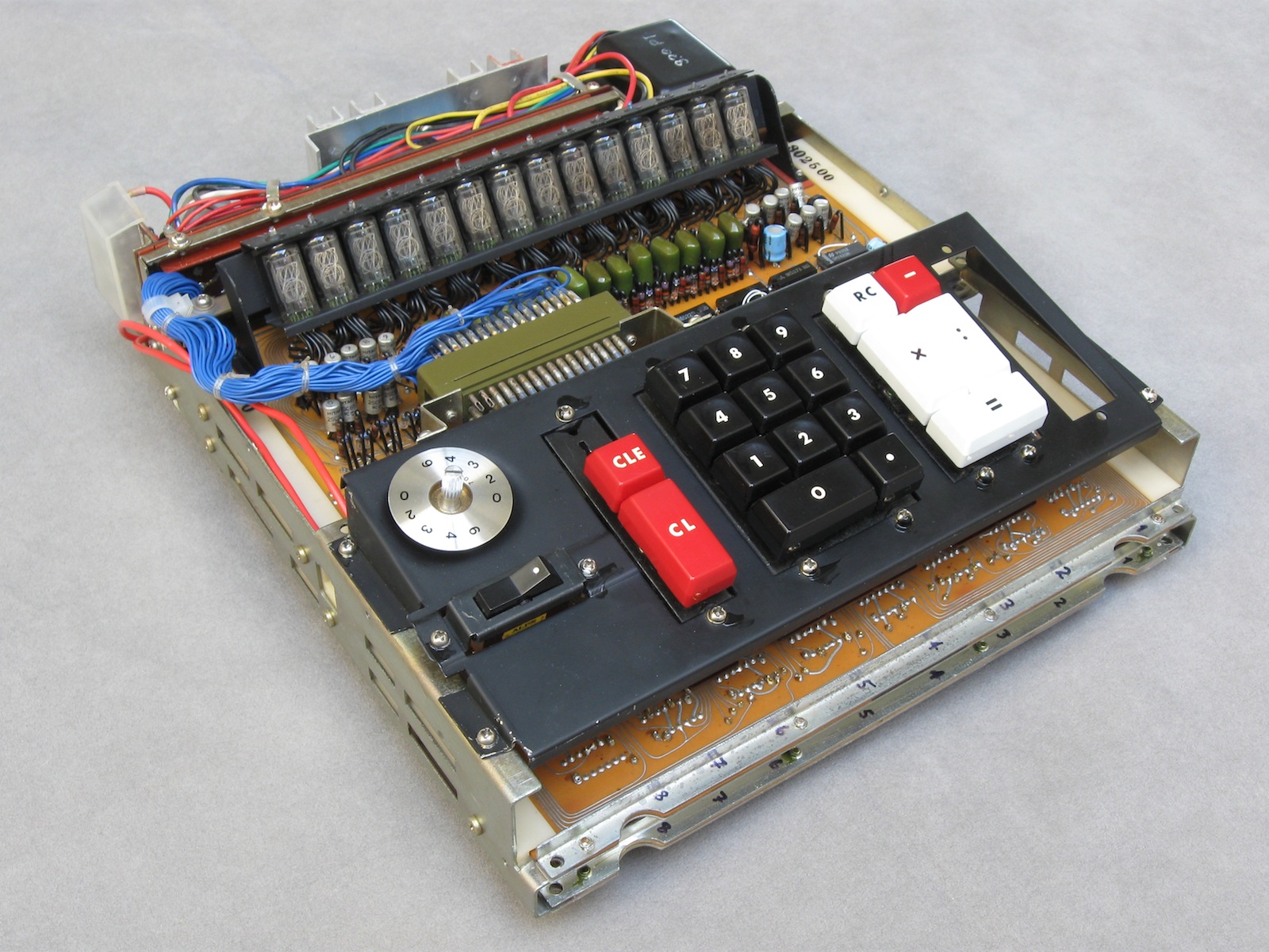
The electronics package removed from the case. There are 3 plug-in circuit boards in a frame, with the power supply at the rear. |

Board 1 / upper. Master clock, digit timing, and Nixie display with drivers. The ICs in the 1123 are from a small/proprietary DTL series. On this board, two ICs have been replaced with 7400 series TTL to effect repairs. The H.E.C. in the foil would be Hayakawa Electric Co. (Sharp). |
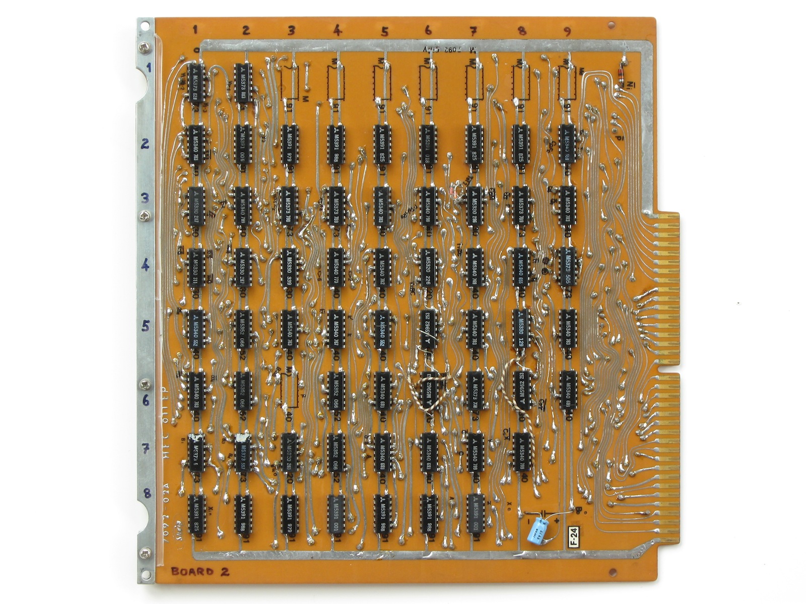
Board 2 / middle. This is primarily the data-processing logic: main registers, ALU, and the decimal-point register. The M5391 ICs in rows 2 & 8 comprise the two main registers (7 * 8-bit shift registers). The empty IC locations in row 1 are for a third, 'memory' register option, included in a higher-end model. |
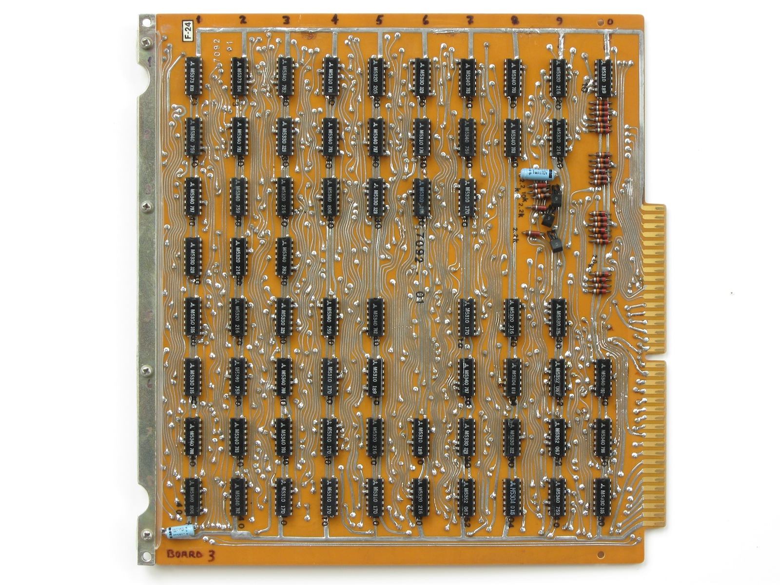
Board 3 / lower. The control / state machine logic, and keyboard encoder and flags. |
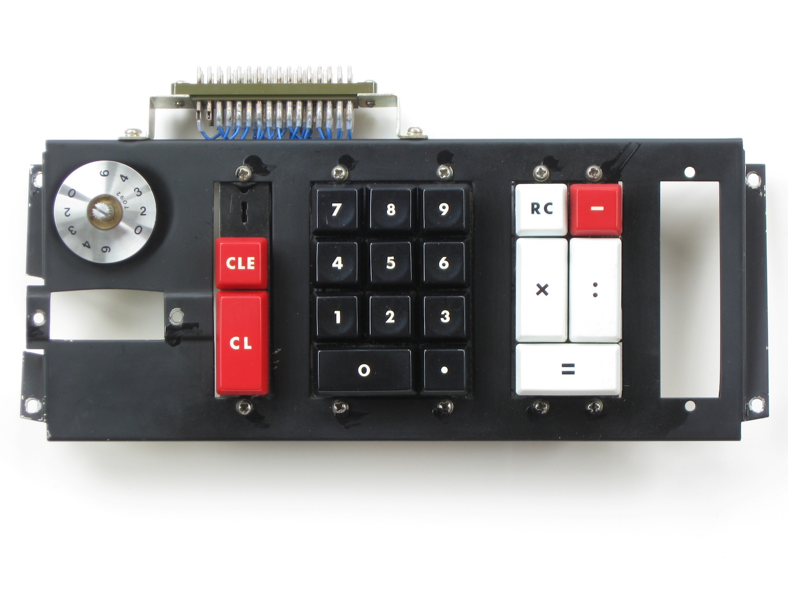
The keyboard is also a pluggable module. |

Keyboard from below. The keyswitches are of the magnetic-reed switch type. |

The power supply seen from the rear of the empty frame. The connector for the CMU (Controller/Monitor Unit) is partially visible behind the mains connector. |

A simple Controller/Monitor Unit (CMU) can be plugged into a service connector on the bottom of the calculator. The switch selects normal or manual operation. In manual, the calculator stops after every major state cycle. The state of the machine can then be inspected, via the display and/or scoping. Pressing the CLE key continues processing for another state cycle. For example in multiplication, the sub-operations of addition and shifting can be stepped through one at a time. In the photo, the calculator is part way through the multiplication 567*123. The 7 of the multiplier (567) has been shifted out of the lower end of the display into another 4 bits of register, where it is being decremented while controlling additions of the multiplicand (123). The product is building in the upper digits of the display, here the 6th addition of the multiplicand, out of the 7 for this digit of the multiplier, has just been performed: 6*123 =738. |

The Controller/Monitor Unit, along with a similar CMU for the Sharp Compet 17. The terminal pins present some useful test points for scoping. These CMUs were constructed after reverse-engineering the calculators, and then assessing what the otherwise-unknown connector on the machines could be used for. The CMU schematic is included in the EEC schematic for the respective calculator. |
| 302.500 | |
| 1969 (transistors stamped with 9C, capacitors with 6850) | |
| 1970s | |
| Crestwood Kitchens discard. | |
| Flaky, can't add. | |
| Fully functional (Apr 2000). |
| Jul 1996 | |
| No display. | |
| Master clock signal enters IC112 but does not exit. | |
| IC112 replaced with 7400, rotated to accomodate differing pinouts. |
| Jul 1996 | |
| Portions of Power Supply rewired. |
| Jun 1997 | |
| DISP line on board 2 open due to corrosion of copper, patched. |
| Jun 1997 | |
| Multiplication and division are okay, but addition results in double the correct sum. | |
| OCC connection to IC380-11 (X Register) open due to incomplete insertion of jumper connecting the two sides of the board at pin 380-11 (manufacturing flaw). | |
| Resoldered. |
| Apr 2000 | |
| Multiplication and division produce erratic results. | |
| Power supply determined to be unstable over warmup time. | |
| VCC rectifier diodes and zener replaced. |
| 23 Jun 2003 | |
| IC112 replaced again with M5340 removed from obscure service unit circuit board. |
| 06 Nov 2004 | |
| Controller/Monitor Unit constructed. |
| 05 Oct 2005 | |
| Left on overnight. Display shows all digits with multiple numerals. No response to keypresses. 6 LSD Nixies dimmer than others. | |
| Digit timing not functioning properly. '8' bit of digit counter not toggling. Resistance on IC142-2 circuit lower than others. Low resistance traced to input IC162-13, which sinks 85mA when tested after removal. IC142 also failed. | |
| IC162 (5320) replaced with 7420, IC142 (5373) replaced with 74107. In this circumstance the 74107 is more pin-compatible with the 5373 than is the 7473. |
| 06 Oct 2005 | |
| nOD0 observed on scope to being influenced by the main clock (high level being pulled down near but not quite to low threshold at main clock frequency). | |
| Input IC229-3 shows non-linear impedance to pin 2. Upon removal pin 9 or 10 also measures faulty. | |
| IC229 (5340) replaced with surplus 5340. |
| 24 Sep 2020 | |
| Multiplication observed to not always be correct: 125*3=379, although 3*125=375. | |
| From the CMU, failure is taking place on the 4th of 5 additions of 3: 3-6-9-16-19, rather than 3-6-9-12-15. Vcc is 5.21V, tweaking it up just slightly (5.23), corrects the problem. | |
| Left for the time being, something is operating on margin, probably in the ALU sum-correction logic. |
| 25 Sep 2020 | |
| Nixie of 6th LSD digit not lighting up. | |
| BE short in A429 driver transistor. | |
| 2SA429 driver replaced with 2SA618 from Nixie display board from scrapped unknown service unit. |
| 09 Oct 2020 | |
| Continued from 24 Sep. | |
| Problem reduced to 9+3=16, 9+4=17, 9+7=1A[2,8],9+8=1B[3,9]. A spreadsheet setup shows the problem is coincident with an improper sum-correction carry being generated when the '2' bit of the raw sum is 0. Use of the simulator confirms this can occur when U257.6 is held LOW or U257.4 (or either of the two U256 inputs it drives) are held HIGH. | |
| Jumper wire for U256 M5962 substitution (U257.4->U256.2,11) had come loose from poor tack soldering (manufacturing). Jumper replaced. Some other jumpers from M5962 substitutions also replaced. |
| Oct-Nov 2020 | |
| Continued from 09 Oct 2020. Previous repair did not fully fix problem. Multiplication and division produce random whacky results. | |
| The fault remains sensitive to the Vcc level. When Vcc<=5.06 problem occurs, but unit works when Vcc>=5.10. An assessment on 17 Nov 2020 shows Vcc<=5.13 Fail, Vcc>=5.19 OK. Problem is likely occurring during states states 31, 32 or 33. For further investigation, should add monitor LEDs to state register so state can be observed while under CMU control. Left for time being, functional with Vcc=5.19V @ 13.5C. |
|
Facit 1123
Calculators | Integrated Circuits | Displays | Simulations EEC |
bhilpert |