|
|
|
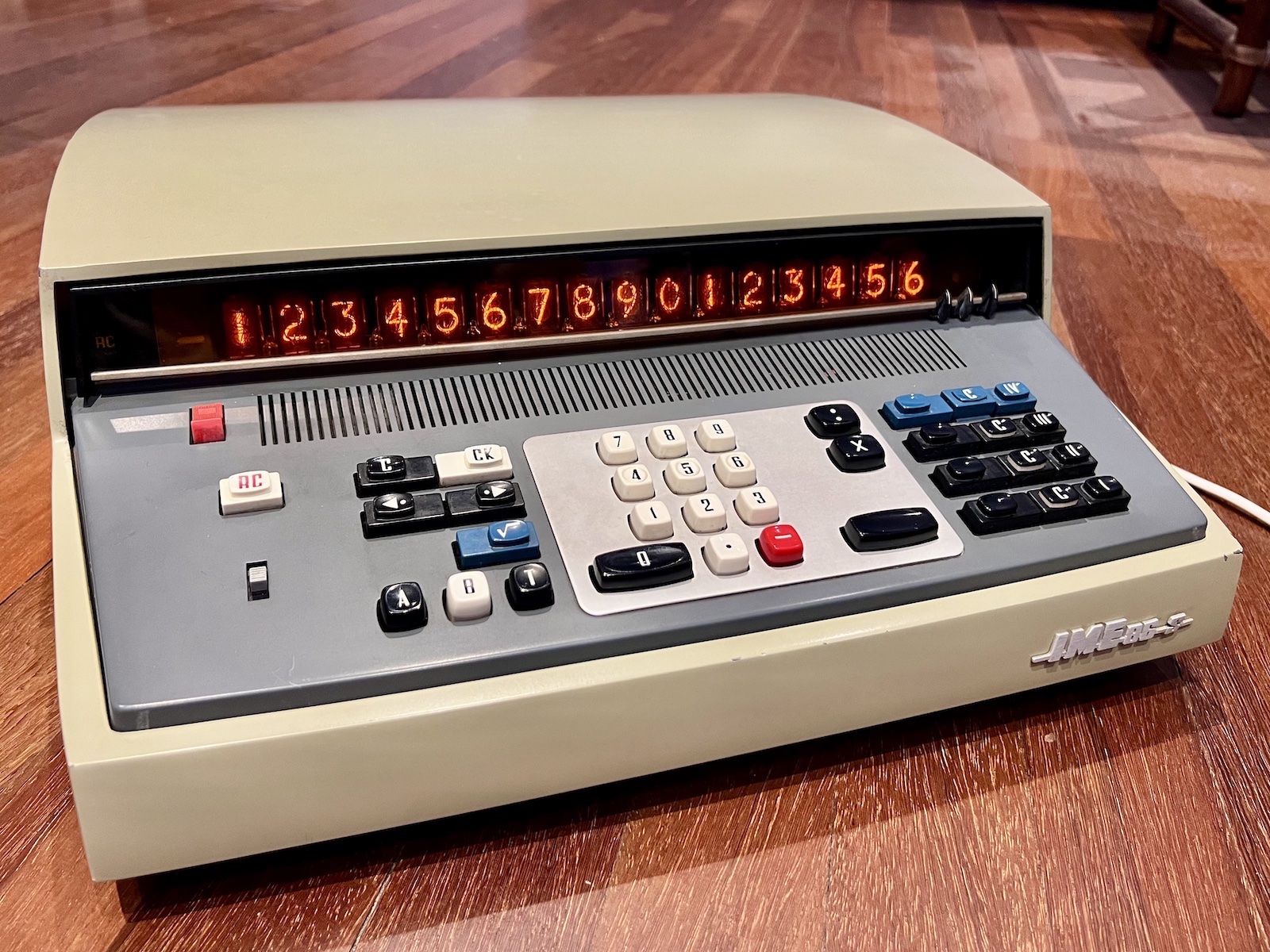
The IME 86S was a follow-on to the IME 84. It is the same physical format and discrete-Ge logic with core memory as the 84, but takes a big step away from the mechanical-heritage user interface towards a simpler and more intuitive algebraic entry, and has 3 more user memories.
The core memory in the 86 uses a 2-1/2D,2Wire organisation with a novel use of a charge-pump for power supply to the core. See the Theory of Operation for more detail.
(Photos & possession / Jef Ongena.)
| Notes: |
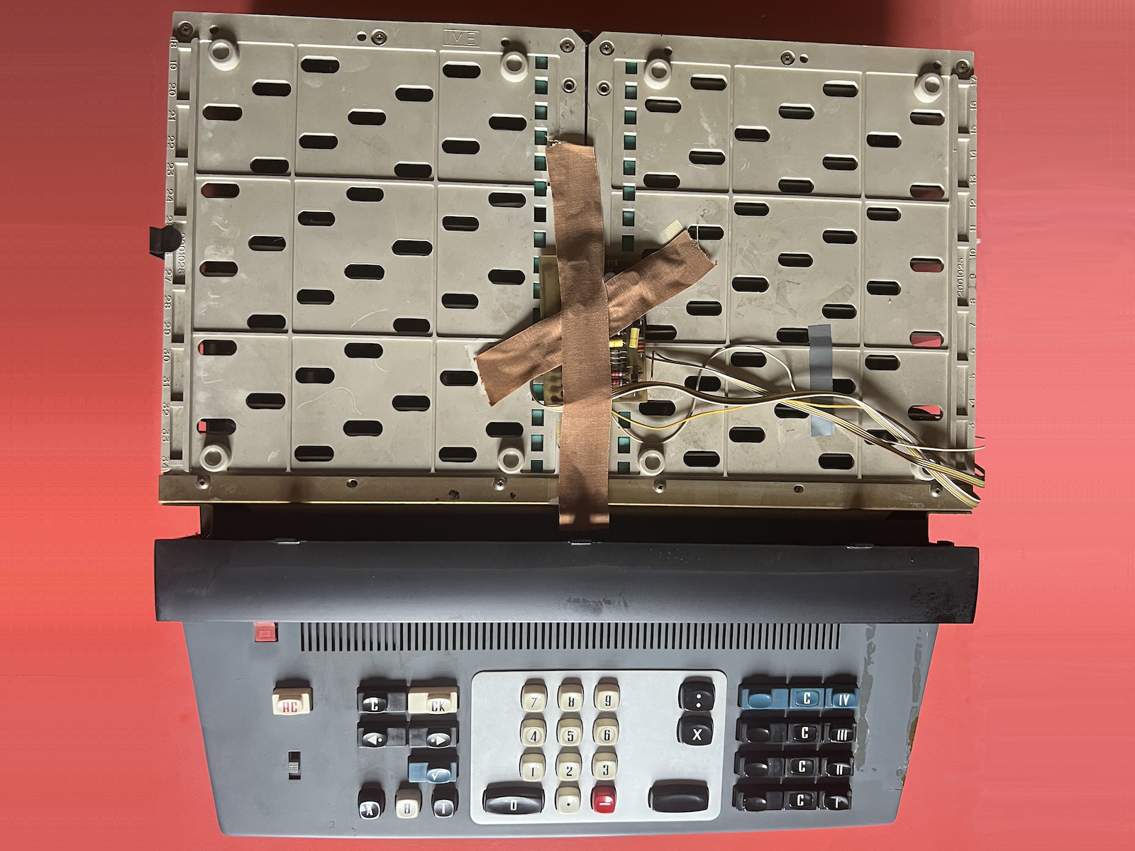
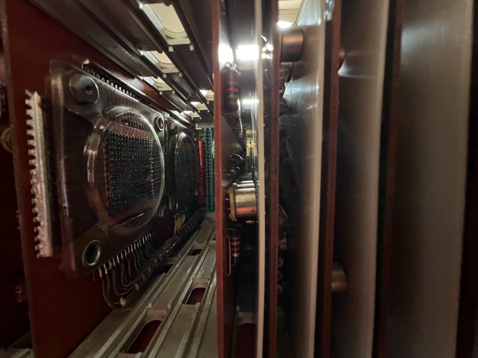
The double card-cage will swing open for access to the backplane. The small board taped to the top of the card-cage is the 4m modification to adjust the negation behaviour. |
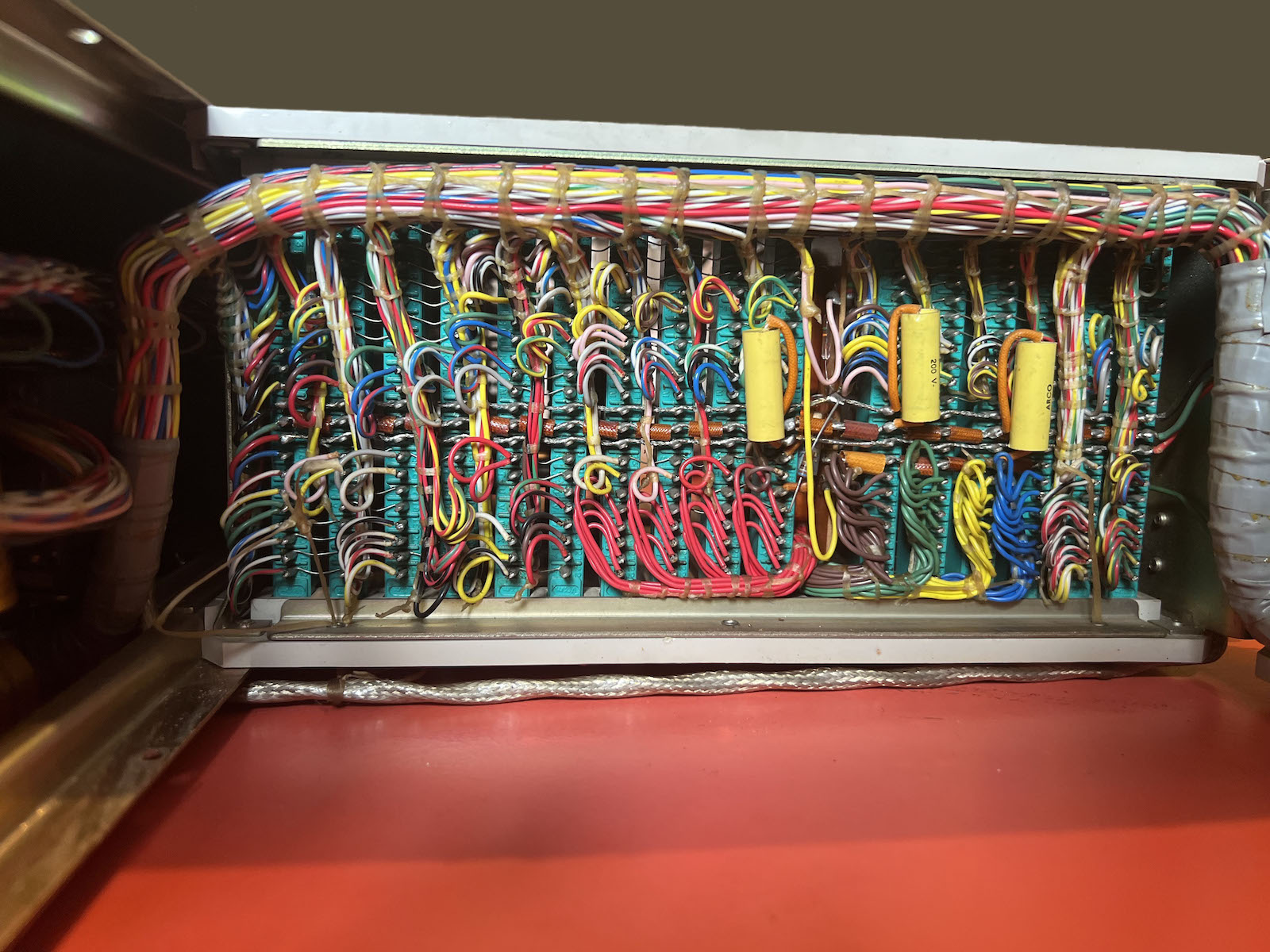
The left half of the hand-wired card-cage backplane. |
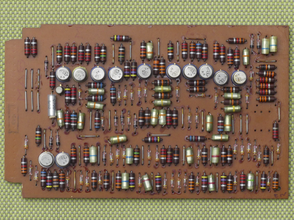
An example of the logic boards. This is board 3 containing the FKP, FEX, FEEN & FESH flag flip-flops. |
The core memory as installed in the card-cage. |
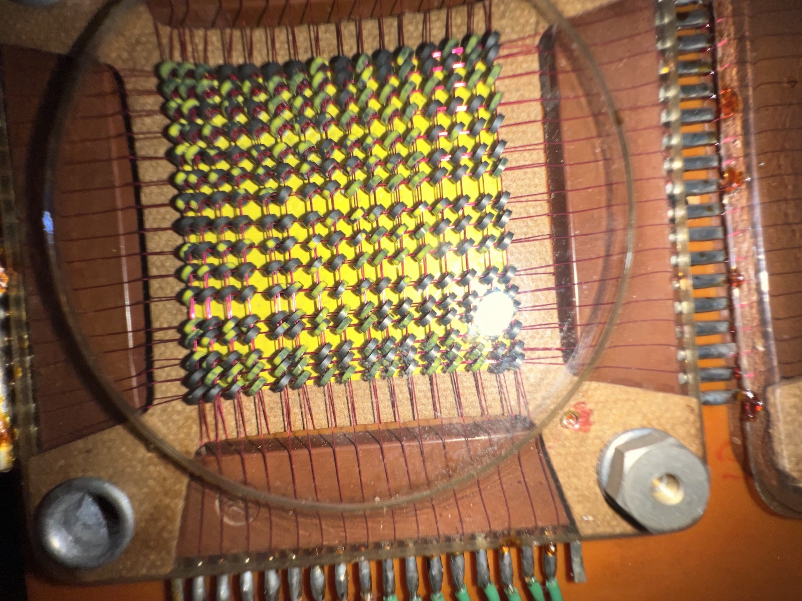
One half of the core memory. This is storage for 2 of the 4 bits of each of the 16 digits of the registers. This is a 2-1/2D,2Wire scheme. The horizontal wires are the digit-select lines. The vertical wires are a combined register-bit select and sense line. Each vertical column is 1 of the 4 bits of the digits of a register. While it appears each core has 4 wires going through it, it is actually a double loop of the wire on each axis. This permitted halving the current requirements from the drivers. |
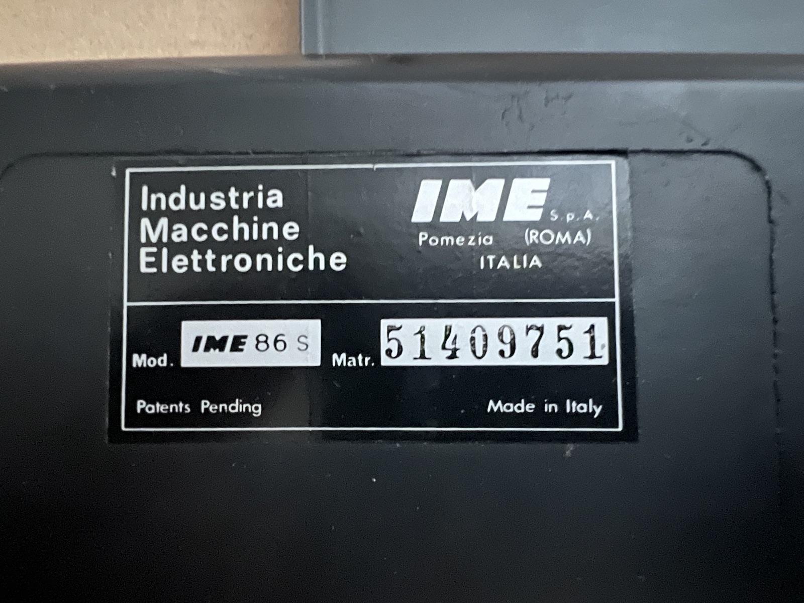
ID plate of this unit. |
| 51409751 | |
| 1966 (sample transistor date codes 6551,6449) | |
| 2024 | |
| Remote assistance to J.Ongena. Physical repairs by J.O. | |
| Largely functional but hangs on square root and several other faults per repairs of 2024 Sep.
A small board labeled "Minus Logik" is present taped to the top of the card cage and wired to board 4. |
| 2024 Sep | |
| Several DP neon lamps flickering or not illuminating. | |
| Replaced. |
| 2024 Sep | |
| 6th Nixie from right ghosts numerals from other digits. | |
| Anode driver does not turn off, likely BC leakage. | |
| Anode driver replaced with MPSA92. |
| 2024 Sep | |
| Broken diode on board 3 at ΦPCL input to AND gate feeding 3.12Nv. | |
| Diode replaced with BAT46. |
| 2024 Sep | |
| Fractional digit entry with DP at 8 F-Ds enters new numeral at 10^12 digit. | |
| - With DP at 8 F-Ds, double pulse occurs on TC=ΦD with the DP entry and then goes away with numeral entry.
This suggests the problem arises during the pulse burst that aligns TC=DP.
During this alignment TC is counting down.
- The double pulses are at TC=8 & TC=12. - TC comparator gate with ΦDC input is supposed to assert when TC=8 (FTC8=1, FTC4=0, FTC2=0, FTC1=0) - Conjecture: with the 4~ diode open at gate, that input is 1, so the gate asserts early, when TC=12 (it thinks FTC4=0 even though it is 1), and TC alignment stops with TC=12 rather than TC=8. Diode measures open. | |
| Diode at 4~ input replaced with BAT46. |
| 2024 Sep | |
| Pressing square root key hangs the machine. | |
| QB signals are persistently active - machine is stuck in QB loop. F32 is stuck 1, so no 0-edge to terminate QB. Diode for (I8~=>SG~&SC3=>SK~) input-pair of F32 failed open-circuit. | |
| Diode replaced with BAT46. |
| 2024 Sep | |
| Operations to Memory IV produce incorrect results, results from square root are also often incorrect. | |
| Square root uses M-IV, so fault is consistent with M-IV problem. Bit-2 of M-IV is always 0. Traced to open BC junction of transistor T22.13. | |
| T22.13 replaced with 2N2907. |
| 2024 Sep | |
| Accessing M-n for use as an operand leaves the sign of M flipped. | |
| FSM stuck 1. Q~ base gets reset trigger pulse and Q responds by going 0, but state does not hold. | |
| FSM.Q~ replaced with 2N3906. FSM now holds states properly and will set and clear on NEG keypresses, but intended effect is not apparent. |
| 2024 Sep | |
| Exponentiation results incorrect. Exponent counter increases by 3, result is often for N+1, e.g. 14^2=>15^2. | |
| Inverter 15.10Nv drives GR4INC to increment the exponent count. If the AND gates driving 15.19Nv had an open input diode, increments would occur at additional steps where they shouldn't. Diode at QMC input failed open. | |
| Diode replaced with BAT46. |
| 2024 Sep | |
| Overflow occurs on multiplication if DP is at far right (no fractional digits). | |
| DP=15 when there are no fractional digits. This state is explicitly tested for when multiplying by the AND gate feeding 7.1PL. Diode for F32~ input failed open. | |
| Diode replaced with BAT46. |
| 2024 Sep | |
| For first minute or so after power-on, division (and square root) produces incorrect results. Fault became worse over a few weeks to near-constant. | |
| Incrementing of Z, common to both DV & SR, is functioning well.
However testing with n/9 to give same value in quotient digits,
the length of QB1 assertion where subtract-and-increment is performed varies.
This suggests a problem around the FCS & GASUB area producing bad subtractions and bad sign change indications.
Scope shows GASUB signal from inverter 5.10Nd has weak 1-level that decays into the 0/1 transition region. | |
| T5.10 replaced with 2N3906.
Unit fully functional. |
| 2024 Oct | |
| Numeral entry does not work. | |
| Traced to the FEEN flip-flop. T3.10.BE open, BC shorted. | |
| T3.10 replaced with 2N3906.
Unit fully functional. |
| 2024 Oct | |
| Intermittently, bits do not set 1 in 4th LSD, 8th, 12th. Those digits often remain 0. Problem may go away a few minutes after warm up, then return after unit is off for some days. | |
| ΦDd which addresses those digits is weak going to 1. RC curve on rise to -V (1-edge), and sometimes low amplitude. Something is failing to pull it to -V or something is excessively loading it to GND. Driving signals for ΦDd gate (ΦDC.1 & ΦDC.2) look good. Pull-up R for gate OK. This leaves leaky diode(s) on the many inputs driven by ΦDd as possible culprits. | |
| Diode for one of the high-side core drivers on board 28 replaced wuth BAT46. ΦDd signal improved though still some curve on 1-edge. ΦDd gate-input diode for digit anode driver of 4th LSD (T28.1) shows variability with cold spray. Diode replaced with BAT46. ΦDd signal now consistent in shape with other ΦDm. |
| 2026 Apr | |
| When cold, numeral entry in the MSD may fail for numerals 8 & 9: 8 becomes 0, 9 becomes 1. Also when cold, MP,DV,SR operations may produce erratic results in the lower digits. | |
| During the numeral-load number-cycle, the 8-bit is successfully written to core from DZ.
The sense pulse shows up in the next number cycle, but FX8 fails to hold the 1,
being cleared shortly after setting in ΦD15.
T32.8.B (FX8.Q) observed to be at BE V (-V) even when T32.8.C is -V (1) and T32.9.C (Q~) is 0. This implies T has weak base current taking it slightly linear, due to leakage from somewhere. FX8 transistors and FX8.SK~ diode and C replaced to no benefit. | |
| Diode for FX8.SE~ input replaced with BAT46.
T32.8.B V is now as expected. Both faults are resolved. The triggerring of the bad behaviour was not traced but is anticipated to have been noise being amplified by T32.8 being in the linear operating region, leading to mistriggerring of FX8 (much like the FSM7 fault in the IME84). A larger noise pulse may be occurring during φD15 and was the first to instigate mis-triggerrings. |
|
IME 86S
Calculators | Integrated Circuits | Displays | Simulations EEC |
bhilpert |