|
|

|
I suspect the LSI chip-set utilised in this calculator is an example of Rockwell's first version of the PPS4 processor series. This speculation is based on some correlations with ICs from the later PPS4/2 version.
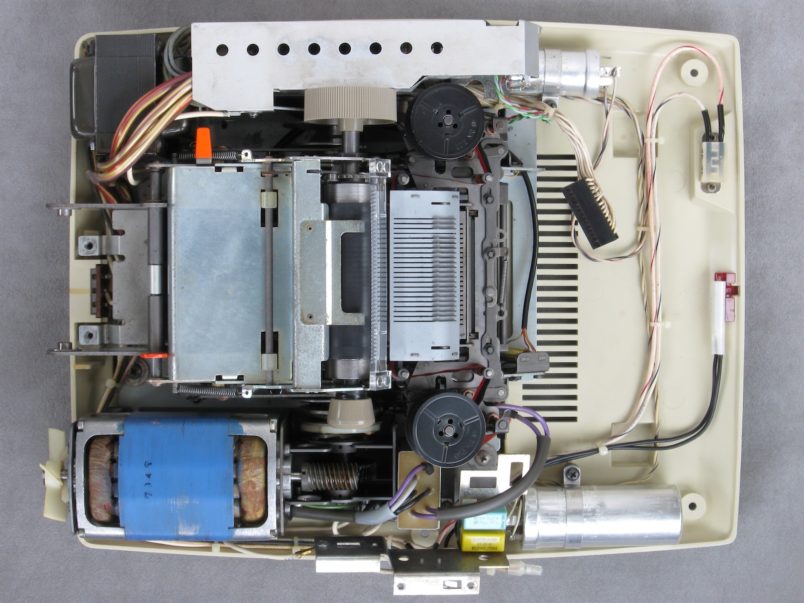
Internal view. Upper half of case removed. |

Print mechanism and insulating separator between mechanism and logic board removed. |
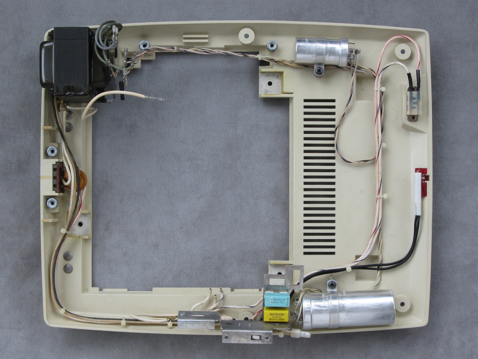
Lower half of the case with the print mechanism and circuit boards removed. |

Upper half of the case with keyboard. |
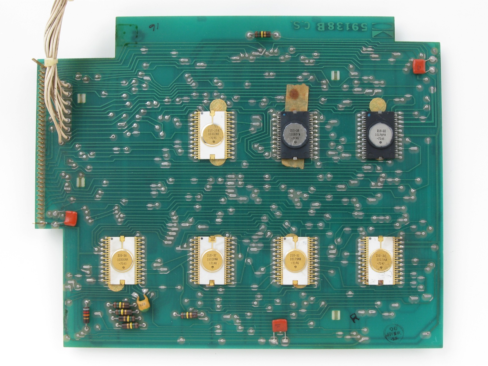
The logic board with the Rockwell chipset. |

Logic board solder side. |
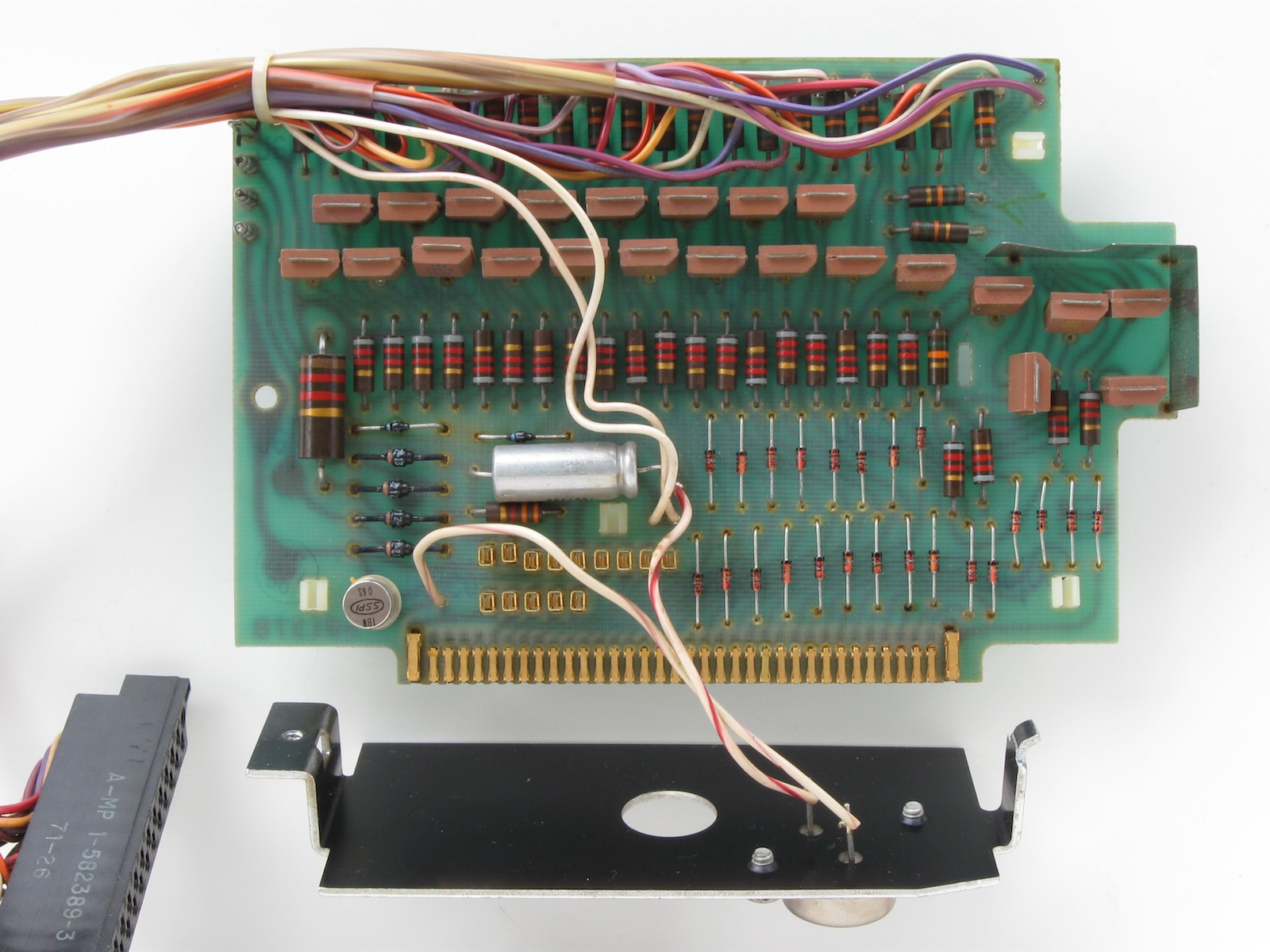
Driver board. The reddish-brown transistors are integrated darlington pairs to drive the print solenoids. |

Driver board solder side. |

Power supply board. |

Power supply board solder side. |

The print mechanism. The mechanism appears to have been in some measure adapted from that of a mechanical calculator. There is a solenoid for every digit. In operation, a print cycle is initiated, the solenoids are then triggerred at a point in time to select the numeral to be printed for that digit. All the heavy work is performed by the motor, the solenoids are quite small. |
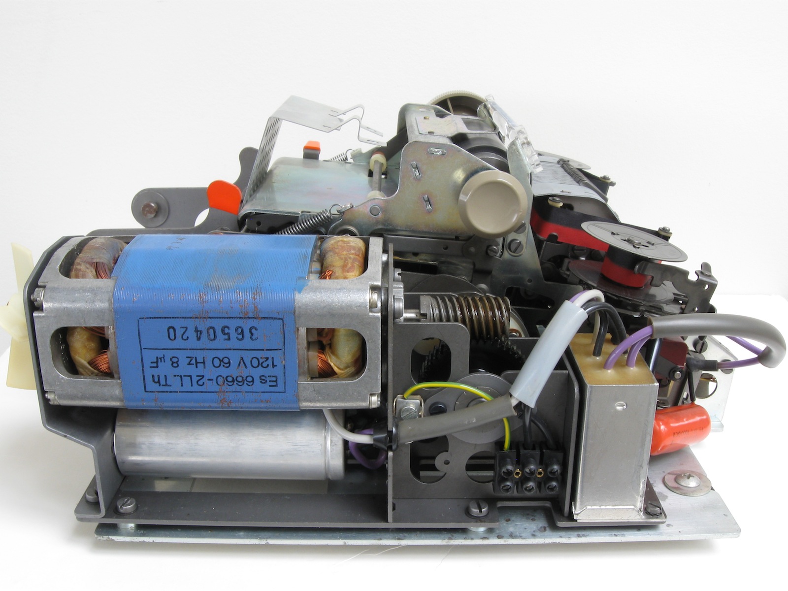
Mechanism left side with power connections for motor. |
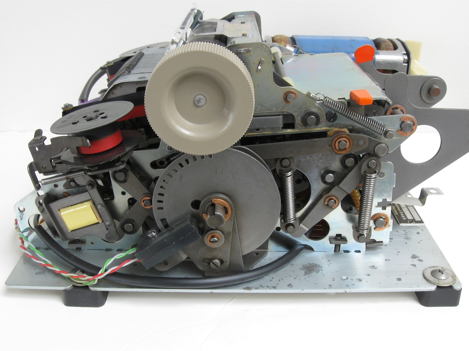
Mechanism right side. The timing wheel and optical sensor send pulses to the logic to time the triggerring of the solenoids for numeral selection. |

Rear of the mechanism with a view into the area where the solenoids are located. |
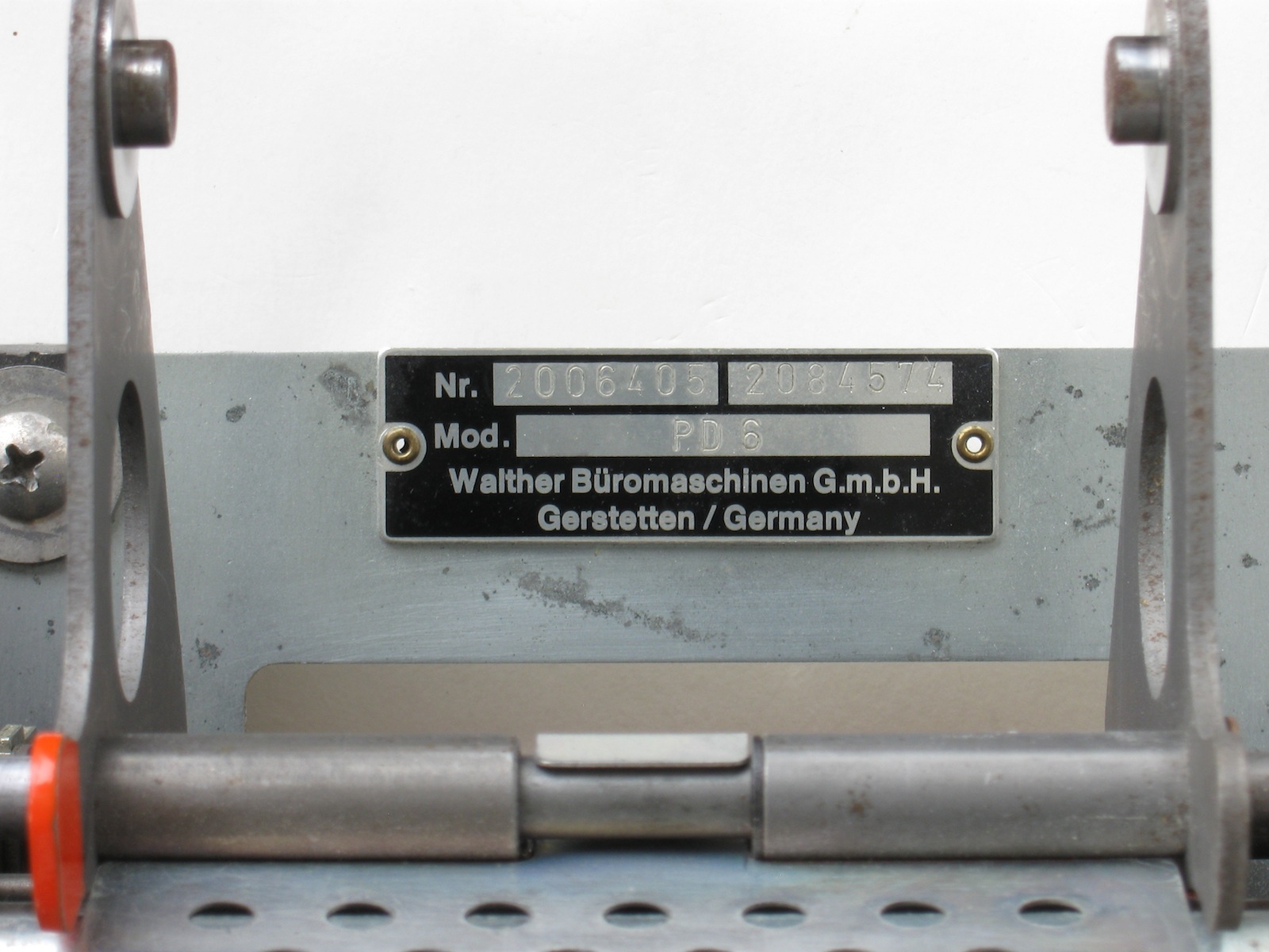
The mechanism was OEM manufactured by a German company. |
| 4173-594 | |
| 1971 (Integrated circuits stamped with 7140 to 7147) | |
| 25 Jan 2001 | |
| Haggerty warehouse. | |
| Very grubby from storage in industrial warehouse. Non-functional. | |
| Fully functional (31 Jan 2001). |
| 30 Jan 2001 | |
| Cleaned extensively. Plastic pegs holding power switch replaced with flat-head screws. Line-supply wiring redone. |
| 30 Jan 2001 | |
| Infrared photo-emitter and associated dropping resistor burned out. Value of resistor unknown. Both replaced. Unit now functional. |
| 31 Jan 2001 | |
| Paper slipping during feed operations and skewing to one side. | |
| One corner of paper pressure plate observed to be bent up slightly, causing paper to bind between plate and platen. | |
| Corner bent back down while dismantled for cleaning. |
| 15 Feb 2021 | |
| LSD very light or not visible. Seems to be active but may not be striking hard enough. |
|
Victor 18-3441
Calculators | Integrated Circuits | Displays | Simulations EEC |
bhilpert |