| Manufacturer: | IME |
| Model: | 84 |
| Year: | 1964 |
| Form: | Desktop |
| Functions: | Basic four, 1 user memory |
| Number of Digits: | 16 |
| Display Type: | Nixie |
| Logic Technology: | DIS |
| Memory Technology: | CORE |
| Diodes: | 1045 |
| Transistors: | 408 |
| Tech. Data Level: | 3 |
| Tech. Data Source: | RE |
| Tech. Data Pages: | 26+24 |
| Tech. Data: | Schematic, Theory of Operation |
|
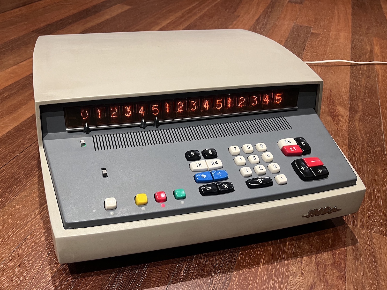
The IME 84 is one of the very first electronic desktop calculators.
IME was an Italian manufacturer - Industria Macchine Elettroniche.
In the user-interface and higher-level architecture this early machine is largely an electronic mimic of the desktop mechanical calculators of the day.
For example, there are separate equals keys for multiplication and division in addition to the add/subtract totalling key,
and the arithmetic is counter-based rather than using a binary adder.
The 84 is implemented with Ge discrete-component logic and core memory.
The core memory uses a 2D,2Wire organisation with one axis of wires shared for address and sense,
obtaining some economy over the more-common 3D,4Wire form.
See the Theory of Operation for more detail.
The IME 84 was followed 2 years later by the improved IME 86S.
(Photos & possession / Jef Ongena.)
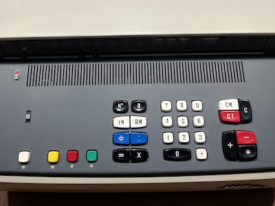
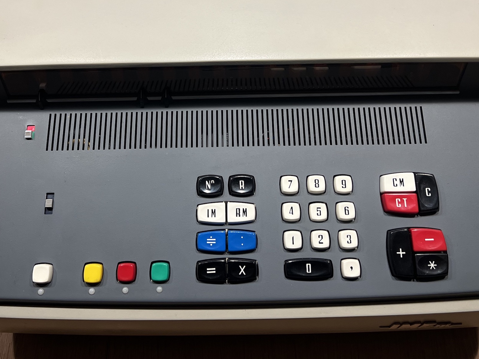
Notice that multiply and divide have their own equals keys.
This is a legacy of mechanical desktop calculators, it allows for a simpler control system.
|
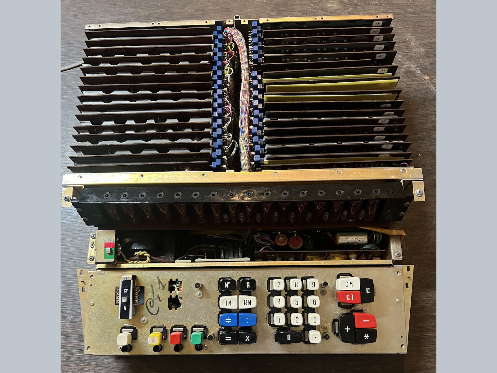
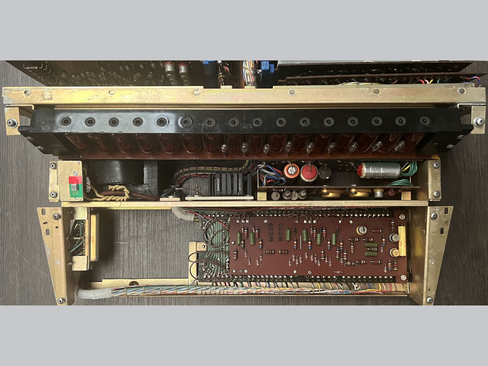
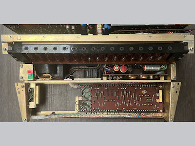
Internal view.
|
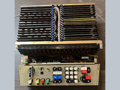
Keyboard removed; power supply and keyboard-logic boards visible.
|
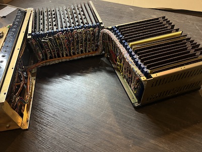
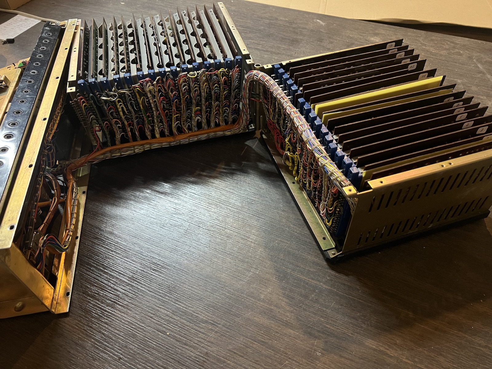
The card-cage is hinged and swings open to access the backplane.
|
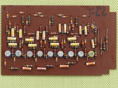
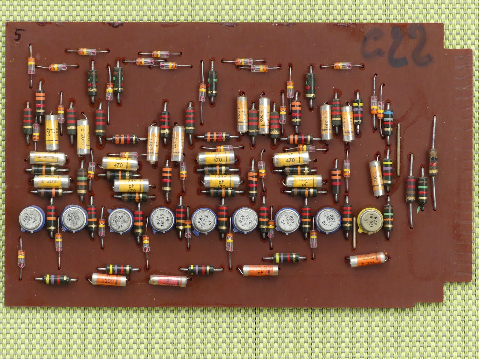
An example of the logic boards.
This is board type 66, containing one of the register decade-counters constructed from 4 flip-flops.
|

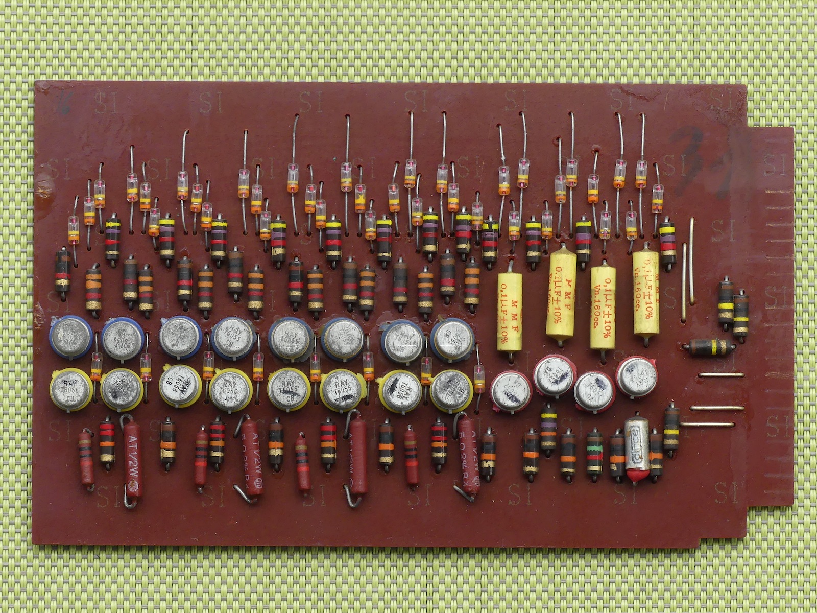
This is board type 72, containing 4 digit-line drivers to the core memory and 4 nixie anode drivers.
|
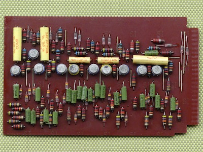
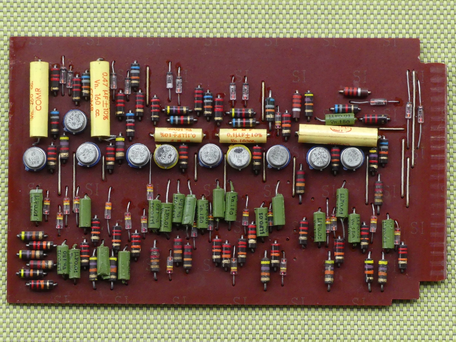
Some of the higher-level algorithm control logic of the 84 is implemented from 10 monostables and
numerous pulsers to form a state machine which produces sequences of pulses.
This board (type 92, slot 26) contains 5 of the monostables of this sequencer.
|
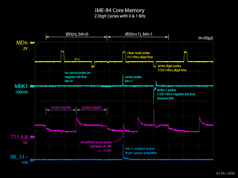
This scoping annotation shows the basic core memory operation cycle.
With RK=10, the 1st two digit cycles were captured, showing the 1 bit of the digits is 0 in the 1st digit and 1 in the 2nd.
|
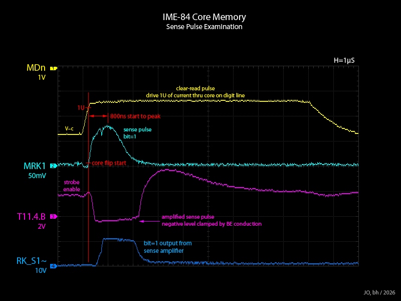
A closer examination of the core sense behaviour.
|
- Unit Log -
| Serial Number: | 1.8400903 |
| Year of Manufacture: | 1964 (sample transistor date codes Moto 3-36,4-12) |
| Date of Receipt: | Correspondance with Jef Ongena / 2025 Oct |
| Source: | Remote assistance to J.Ongena. Physical repairs by J.O. |
| State upon Receipt: | Largely functional but two digits faulty in display, problems with negative values and division. |
| Date: | 2025 Nov |
| Symptoms: | 16th digit (MSD) does not illuminate, 6th digit dim. |
| Solution: | According nixie anode drivers replaced with MPSA92. |
| Date: | 2025 Nov |
| Symptoms: | Total key does not complement sums<0 for proper display, negative lamp does not light. |
| Analysis: | Inverter 18.13Nd stuck 1, even though FNEG is functioning properly. |
| Solution: | Transistor 18.13 replaced with 2N3906. |
| Date: | 2025 Nov |
| Symptoms: | Division does not work. Operands are left unchanged in RK & RA. |
| Analysis: | KOP~ is not asserting, although KOPDE~ does assert.
Diode from D~ into NORN gate for KOP~ pulser gate open. |
| Solution: | Diode replaced with BAT46. |
| Date: | 2025 Nov |
| Symptoms: | Intermittently, RK lamp does not illuminate after an Add or Subtract operation. |
| Analysis: | Contacts for RM- & RB-select switches do not open fully. |
| Solution: | Contacts bent slightly for proper clearance. |
| Date: | 2025 Nov |
| Symptoms: | Intermittently, pressing the Total key where the sum<0 switches the display to RM rather than the correct RA. |
| Analysis: | Scope observation shows FRS1 goes 1 when FPWORK asserts for the complementing subtraction.
A shorted/reverse-conducting diode for one of the two 1~ inputs from FRS to the RSEL_r decoder AND gates
would allow FPWORK~ to feed back to collector-set FRS1.
However, when RK is currently selected, an operation asserting FPWORK does not set FRS1,
suggesting the fault is not the diode for the RSEL_K gate. |
| Solution: | Diode for 1~ input to RSEL_A AND gate replaced with BAT46, this fixes the fault.
Diode for 1~ input to RSEL_K AND gate also replaced with BAT46. |
| Date: | 2025 Nov |
| Procedure: | MOD2025.11 implemented to set DP during summation. |
| Date: | 2025 Dec |
| Symptoms: | Division with a single-digit divisor produces incorrect results.
The result is a far-too-large quotient containing some sequences of the correct digits. |
| Analysis: | With no gap between FPDV1 and FPDV2, at the stage 1=>2 transition, PQC increments to 1 while FSUB remains 1.
The PQC=0 reduction stage is thus skipped and a single subtraction performed, with no add-back.
FPQ1 is being mis-triggerred though the origin is not found.
T21.2 (FPQ1~) noted to have low Vbe in both polarities. |
| Solution: | T21.2 replaced. Two 5nF SE~ capacitors also replaced. |
| Date: | 2025 Dec |
| Procedure: | MOD2025.12 implemented to clear RA when the Divide key is pressed. |
| Date: | 2025 Dec |
| Symptoms: | At low room temperature, calculator presents erratic behaviour with flickering digits and changing numerals. |
| Analysis: | Erratic behaviour traces to pulsing of FSM6 & FSM7 with no apparent external triggers.
The pulses of each initiate in sync, but FSM6 pulses are a subset of those of FSM7.
1-periods are correct for the respective monostable.
FSM7 is simply oscillating at times with a few mS of 0 time.
Cold spray found to instigate behaviour when applied around circuitry of FSM7.
Shorting FSM6.TM~ to GND quiets FSM6.
Shorting FSM7.TM~ to GND quiets both FSM6 & 7, thus FSM6 triggerring is apparently a spurious consequence of FSM7 pulsing.
T27.3 (FSM7.Q) replaced with 2N3906 but cold spray still instigates fault.
T27.4 (FSM7.Q~) replaced with 2N3906 as well. Initially appeared to be successful but problem eventually reoccurred. |
| Solution: | RC timing pair for FSM7 replaced with lower R pair of similar time constant.
See Theory-of-Operation, modification MOD196X.A for explanation. |
| Date: | 2026 Jan |
| Symptoms: | At low room temperature, during number entry,
the number shifts up and the new numeral is entered but the intermediate numerals may be corrupted. |
| Analysis: | FSM10 is being intermittently triggerred.
This can result in an entered value being copied to RM then back to RK during the execution of a numeral entry. |
| Solution: | Q27.9 (FSM10.Q) replaced with 2N3906, on same reasoning as for previous fault. |
| Date: | 2026 Jan |
| Symptoms: | Read (RK) lamp faulty. |
| Solution: | Replaced with LED+500R. |
| Date: | 2026 Jan |
| Procedure: | Loose connection between N26.H & N27.H causing intermittent triggerring of H1 & H2.
Connection repaired. |
| Date: | 2026 Jan |
| Symptoms: | Nn operation faulty. |
| Analysis: | Nn operation is distinguished into two sequences, but at random both sequences may be triggerred to execute together, at the Nn keypress.
When the Nn key is pressed, the trigger pulses from the 3.2 and 8.5 pulsers may be of high enough amplitude that the corresponding
FSM monostable is triggerred even if the pulser is inhibited. |
| Solution: | 68K R-to-GND added to KNn~ line to reduce the trigger pulse amplitude.
(MOD2026.01) |
| Date: | 2026 Feb |
| Procedure: | MOD2026.02 implemented to clear RK when the RM key is pressed. |