|
|

|
This model uses a magnetostrictive delay-line for memory, with a novel technique employed for register management. There are two write transducers on the delay-line at different positions, making a short loop and a long loop. One of the registers cycles on the short loop while the others cycle on the long loop. The register bits on the long loop are injected with an empty bit-slot between them. When they reach the short-loop section of the delay line, the bits of the short-loop register are interleaved with those of a long-loop register by injecting them into the empty bit-slots. This makes it possible to vary which long-loop register will be involved in arithmetic operations simply by making a selection in time rather than doing a full multiplex/demultiplex of all the registers.
Some logic in the keyboard encoding provides for detection of simultaneous depression (rollover) of adjacent keys, to catch some user entry errors.
| Notes: |
|
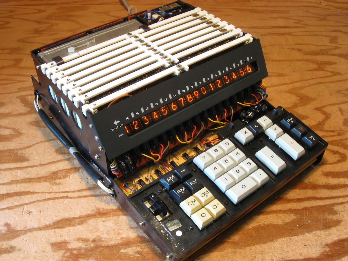
Most of the logic is contained on eight printed circuit boards which plug into a backplane. A small amount of logic is on a ninth PCB below the keyboard, which also holds the keyboard magnetic reed switches. The magnetostrictive delay line is in a sealed metal box associated with the eighth (rear-most) logic board. |
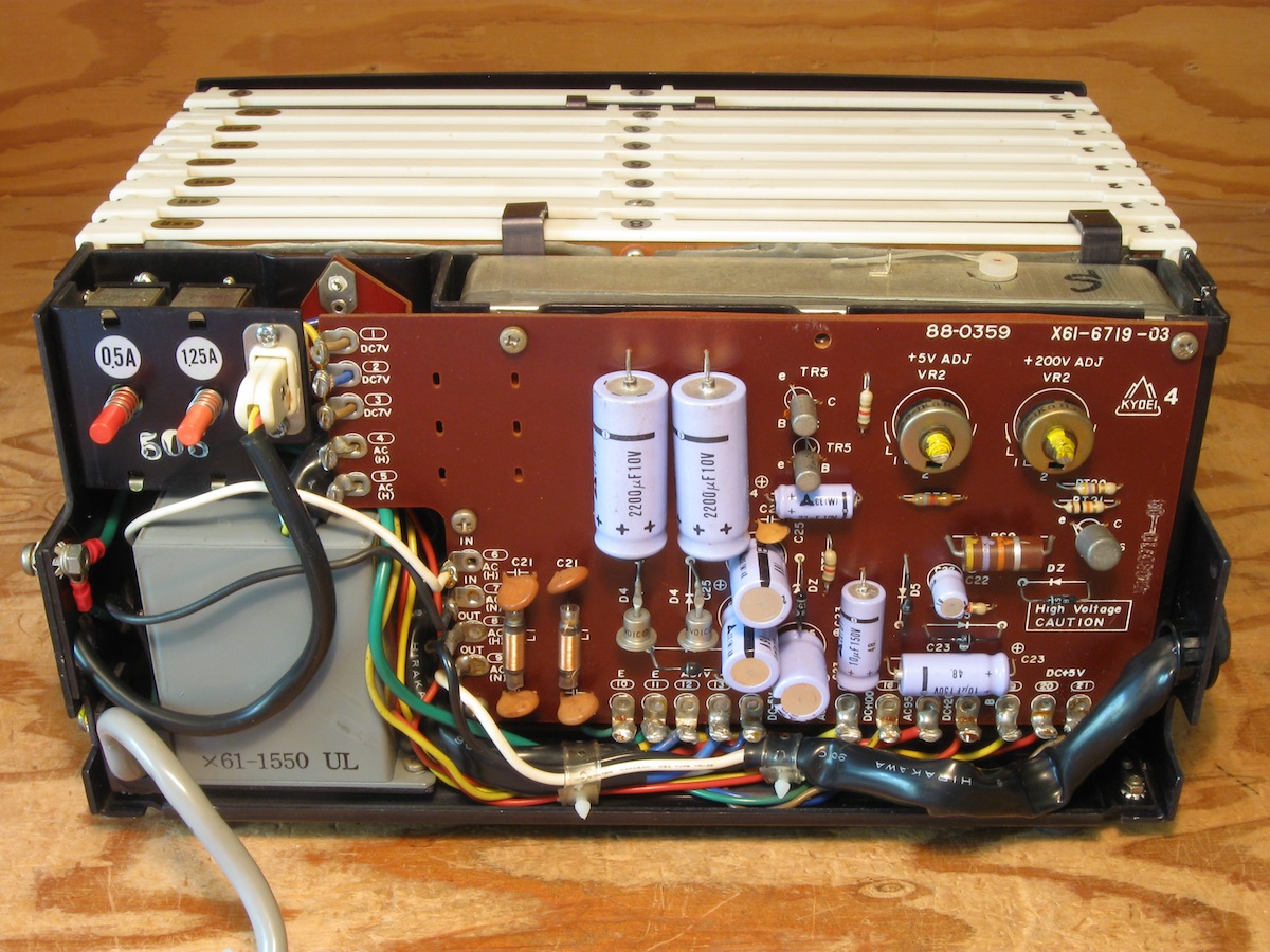
Power supply at rear. Basic linear 5V regulator. |
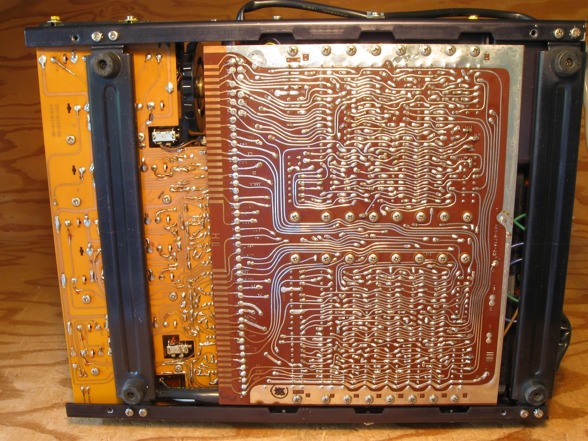
The backplane seen from below. |
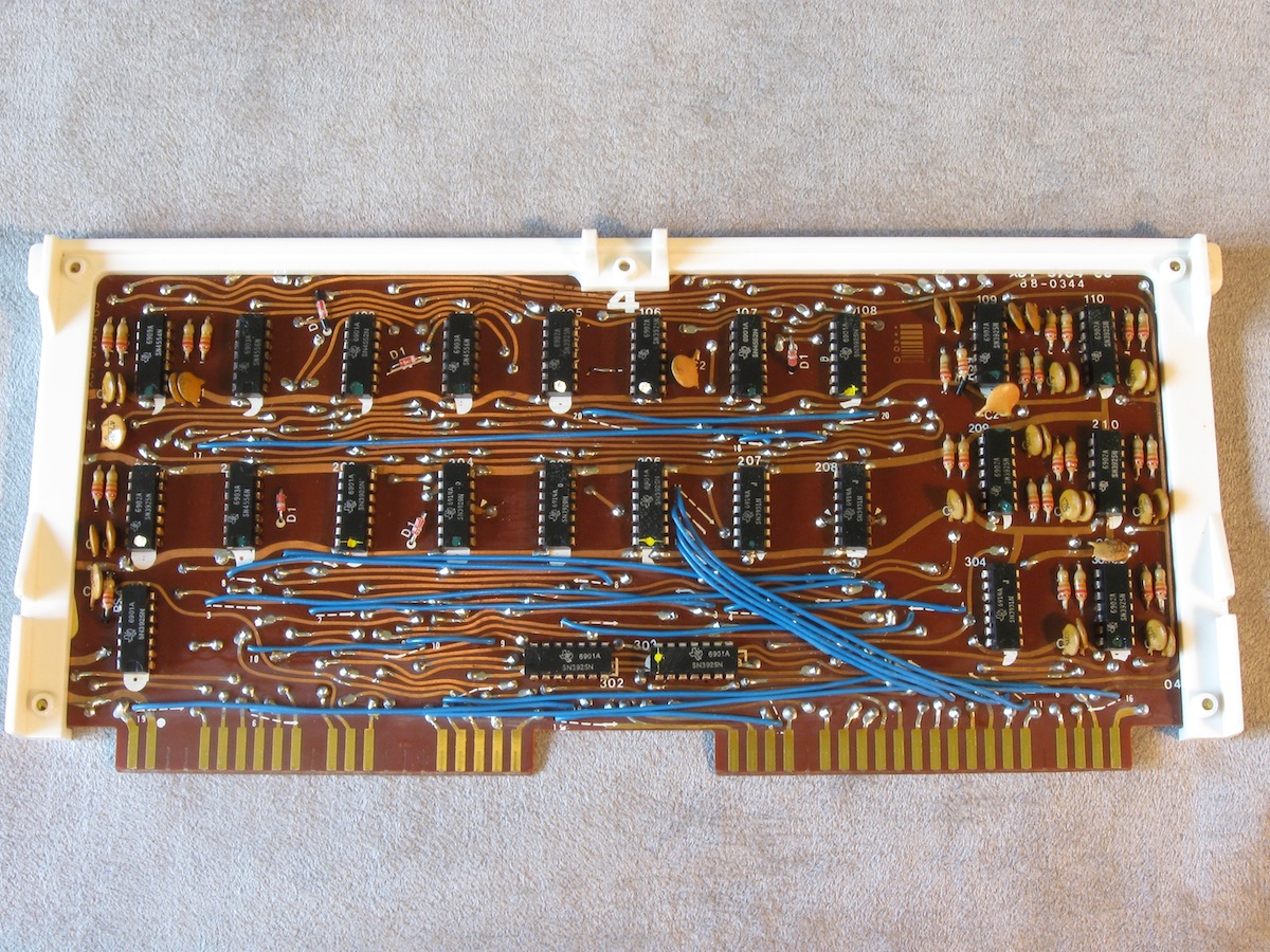
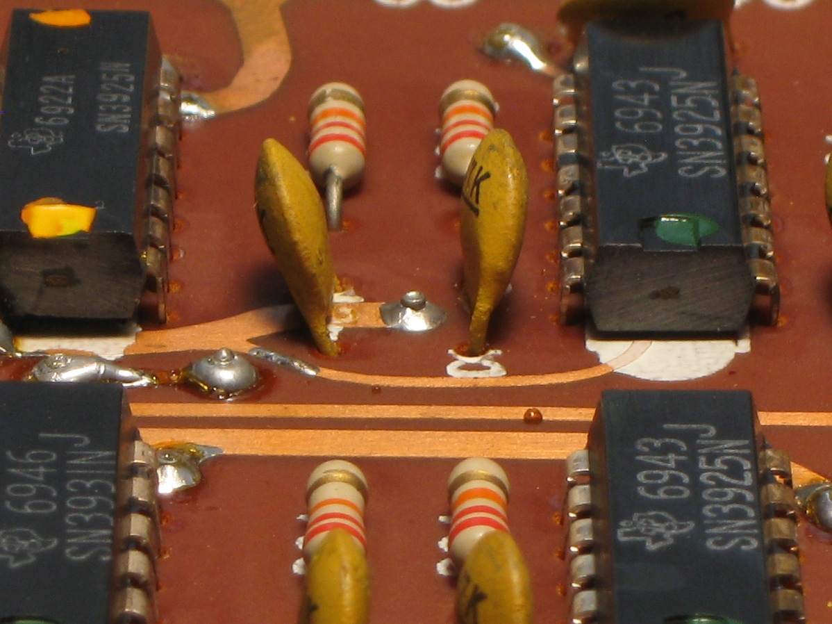
Board 4, an example of the eight logic boards. |
Example of a poor solder connection at a feedthrough stub. The stub connects traces on the two sides of the board. The connection through the stub here is an open circuit. This sort of poor soldering is a common failure in this model and some other Canon models of the same period. (00-8107.14) |
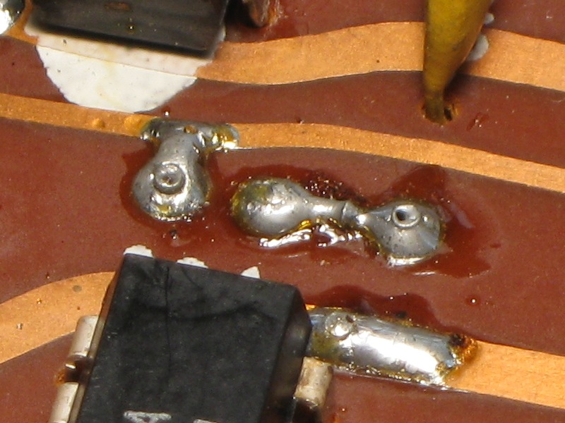
Another bad feedthrough stub example. The right-most stub connection is faulty. Probing for resistance measurement between the top edge of the pin and the solder around the pin shows an erratic ~ 12Ω. In contrast, the left-most stub is OK (at this time). (00-8305.6) |
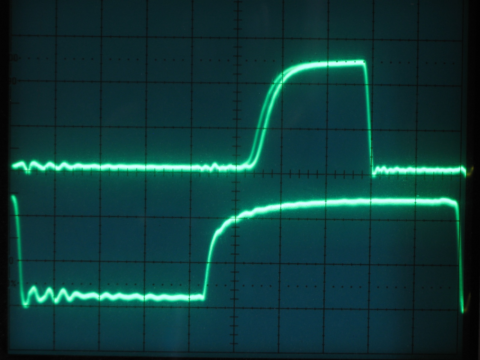
Read-pulse reception from the delay line. The lower trace shows the 2µS read window for pulse reception (IC pin 8101.3). Flip-flop M is cleared on the -edges at the left & right of the trace. The upper trace shows an amplified 1-bit received from the delay line (8103.4). M is set on the +edge of the pulse. H:200ns/div,V:2V/div |
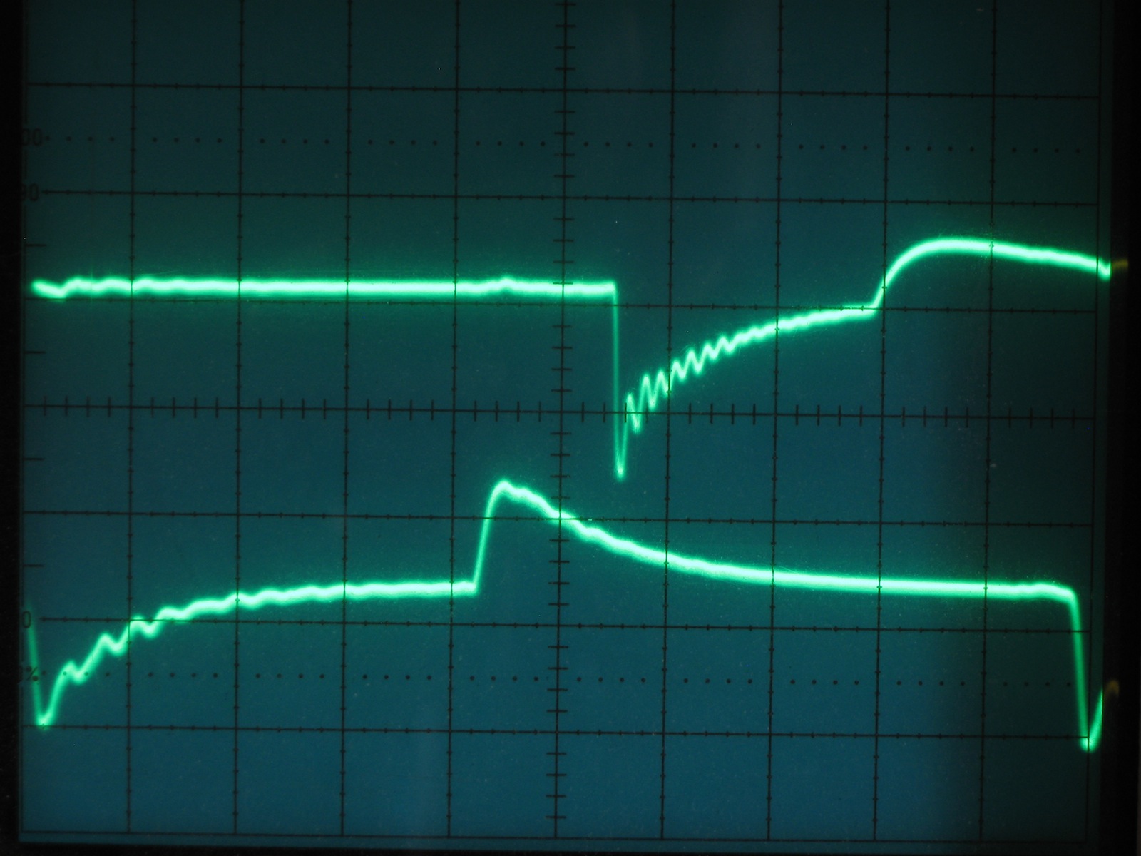
The SR pins of the M flip-flop (8103.10,8103.13). The pins are biased to mid-Vcc, the differentiated negative pulses from the trigger caps set and clear the FF. H:200ns/div,V:2V/div |
| 122900 | |
| 1969 (Most ICs stamped with 6901-6914, ICs on board 2 a little later: 6946 latest.) | |
| 2004 Dec 17 | |
| SPARC surplus. | |
| A little grubby, some corrosion on steel sheet surfaces and on numerous screws. Several of the PCBs appear to have seen repairs by resoldering of many of the connections. Operation results are incorrect when first powered up. OK after warming up for awhile. SQRT(2) initially resulted in 1.417... | |
| Fully functional (2014 Apr). |
| 2004 Dec 17 | |
| Boards reseated. Flakiness reduced. |
| 2004 Dec 21 | |
| Dismantled for cleaning. Keycaps polished to take off yellowed surface. Foam pad beneath keys had turned to tar, cleaned off. |
| 2005 Jan 18 | |
| Cleaning completed, reassembled with new screws and hardware. Foam pad for keys should be replaced so keys have a softer stop when depressed. |
| 2005 Jan 18 | |
| No response to keyboard other than clear keys. | |
| nKCM2 signal is being held active because the reed switch for the CM2 key does not release (open) after the key has been pressed. Pressing the key up from the bottom an extra fraction of an inch will release it. Apparently the reed switch was not fully inserted during manufacture, so the magnet does not travel far enough up the reed switch to release it. | |
| Reed switch unsoldered and pulled closer to the circuit board before resoldering. |
| 2005 Jan 20 | |
| Arithmetic operations produce incorrect results most of the time: anything added to itself results in 0, various single-digit operations are incorrect (3+1=2), multiplication, etc. result in values such 90909090... | |
| Single-digit errors suggest that the carry is not propagating during addition. Observation of output of CA flag shows that while the carry pulses are present, they do not go all the way to ground, but only down to about 2V. Similar behavior observed on the other outputs from the same IC (8104). Ohmmeter indicates poor connection between IC 8104 pin 7 and ground (varying from 6 ohms to open). | |
| Component-side of feed-thru for ground pin of IC 8104 resoldered. |
| 2005 Jan 25 | |
| Delay line read-head position ("R" hole on delay line) adjusted to test limits. Reset such that pulses exit delay line around positive edge of CPR, as measured at pin 8103-6, at approximately 15 deg C. |
| 2005 Nov 26 | |
| Upon power-up, numbers can be entered but operations result in display full of "9"s, also M1 and M2 will not clear (lamps stay on). After some minutes of warm-up, all is well. |
| 2014 Apr 17,23 | |
| Problem from 2005 Nov 26. | |
| Symptoms suggest B data path is OK but A data path is stuck 1 somewhere.
Boards swapped one at a time with those of unit 120234.
Function restored with swapping of board 8 (delay line).
Poor V+ connections found to ICs 8204 & 8205. Resoldered.
9's gone and some calculations OK, but 1+4=>9, 2+3=>9, 2+4=>8, 3+3=>8, 3+4=>9.
Sum correction is failing on bits S2 & S4.
Poor ground connections found to IC 8302 (measures as a few ohms). Resoldered.
Also found poor and resoldered: 8305 GND, 8107 V+.
Problems seem to be at feedthroughs, poor plating & solder adhesion.
Unit now fully functional and seems stable except M1 & M2 lamps occasionally pop on. |
| 2014 Apr 29 | |
| 9's and sum correction problem back intermittently. Seems to be temperature dependant. | |
| nOK signal in sum correction observed to be around 2V (poor logic level). Poor ground connection now found to IC 8106. Stable enough to be confirmed as problem in that jumpering 8106.7 to GND restores operation, disconnecting the jumper restores failure. | |
| 8106 GND resoldered. Unit fully functional again, hopefully that's it for that problem. |
| 2014 Apr 30 | |
| Nope, sum correction problem back very briefly when powered on. | |
| Board 8 placed in fridge to see if temperature dependant. No, lower temp does not induce failure. Poor connection found for OK signal 8106.11 to 8302.2 & 8302.4. Confirmed as problem inasmuch as opening connection reliably produces sum correction failure. | |
| Two feedthrough pins along route resoldered. Unit fully functional again, hopefully that's it for the third time on this problem. |
| 2021 Feb 22 | |
| When powered on, numbers can be entered including both operands for M & D, but actual operation results in 0. Unit functions properly after 10-20 minutes of warm-up. | |
| To do. |
| 2024 Jan | |
| Board 7 edge connectors beveled. |
| 2024 Jan | |
| Display shows all-9s, oveflow, and will not clear. | |
| Speculate that the B loop is open at some point. Traced to open Vcc connection through stub to 8107.14. | |
| Stub replaced with wire and re-soldered. |
| 2024 Jan | |
| Behaviour of unresolved fault of 2021 Feb 22. A number can be enterered and displays, but operations (+=,etc.) result in 0. Intermittent. | |
| Speculate that the A loop is open at some point. Isolated to board 8 with board swapping. Tracing A-loop through sum correction, 8302.11 does not follow 8302.1 even though OK=1. Bad signal level at 8302.3. Poor GND connection for IC through stub to pin 8302.7. | |
| Stub is underneath IC, cannot be reliably resoldered. Pin 8302.7 soldered to GND trace on component side. |
| 2024 Jan | |
| From addition to square root, arithmetic results are incorrect. | |
Testing simple cases of single-digit addition:
| |
| Two stubs in circuit replaced with single wire and re-soldered.
Fully functional. Powered on for several hours, registers stable for duration. |
| 120234 | |
| 1968 (ICs stamped with 6745::6842). | |
| 2011 Jul 02 | |
| SPARC surplus. | |
| Fairly good physical condition, scratch on top.
Zero key sticks down.
Keyboard PCB previously repaired, cracked in area by power switch.
Addition adds extra zeroes corresponding to the decimal point position,
e.g. with DP switch at 4, entering 2 and pressing add results in "2000.0000".
Looks like a problem with decimal point alignment counters in the state machine.
Subtraction/negation do not work, subtract key functions the same as the add key.
Two SN15846 ICs noted at 5105 and 5107. | |
| Fully functional, although DP alignment problem may be intermittent and reappear (2014 Apr). |
| 2011 Jul 03 | |
| Boards reseated. Zero key pulled off, dried grease cleaned, light oil applied. |
| 2014 Apr 19 | |
| Some cleaning of chassis done. Keyboard and case still to be done. |
| 2014 Apr 19 | |
| Boards swapped one at a time with those of unit 122900. Addition function restored with swapping of board 4. Actual problem on board 4 not yet found. |
| 2014 Apr 19 | |
| Multiply does not work, no registration of multiply key. | |
| Traced to bad solder joint where wire from keyboard attaches to backplane. Resoldered. Multiply functional. |
| 2014 Apr 19 | |
| Subtraction results in add. | |
| Works with swapping of board 5. Feedthrough from 5104.6 on bad board 5 resoldered. Improved, basic subtraction works but add/subtract reversed when displayed number is negative. Something to do with SK flag not flipping. |
| 2014 Apr 21 | |
| Continuing from Apr 19, subtraction still not working properly, 2-3+ => -5, 2-3- => +1. | |
| Missing 2nd toggle of SK FF, all inputs to 5207.8 go high except 5207.11. Traced back to SM1 & nSM1, both stuck at ~2V when low. Bad ground connection to 5207. | |
| Feedthrough by 5207.7 resoldered. |
| 2014 Apr 21 | |
| Various problems, numeric key entries occasionally missed, SQRT fails, multiply & divide fail. CLR results in decimal point at various positions. |
| 2014 Apr 24 | |
| Unit fully functional, board 4 DP-alignment issue and others disappeared, DP-alignment comes back temporarily after board taken outside to lower temp. | |
| ADD state sequence determined by scope observation. When error occurs, state 13 is longer by one system cycle while state 12 is reduced by one system cycle (w DP=2). Probably fault around CO flag, needs to fail again to trace. |
| 2014 Apr 25 | |
| Cleaned. Keyboard dismantled and old grease cleaned out, not regreased on reassembly. |
| 2023 Dec | |
| DP-alignment issue returned. e.g.: With DPS=2, keying in "1 2 +" results in "120.00", followed by "5 +" results in "120.0005". | |
| Swapping in board 4 from Unit 122900 restores full functionality. |
| 2023 Dec | |
| Edge connectors on boards 3.1::3.8 beveled to reduce force needed for insertion and likelihood of damaging socket pins. |
| 2023 Dec | |
| Substract operations do not work, although division and root which employ substraction do work. | |
| Swapping in board 5 from Unit 122900 restores subtract. However, after beveling board 3-5, display comes up all 9-0. | |
| Scanning 3-5 with ohmmeter for bad circuits, 5102.7 to GND circuit is open at stub, stub is under IC. Patch wire to nearby GND point soldered in. Board still produces all 9-0, although when moved to 122900 9-0 are gone. |
| 2024 Jan | |
| Returning to board 3.4 DP problem from 2023 Dec and earlier. | |
| HP5480 used as logic analyser. With DPS=4, "1 +" shows 8 iterations in CC13 rather than 5, only 2 in CC12.
FC0 flag noticed to be very sensitive - tiny extra loading (input to 5480) on FC0.Q output will inhibit it from setting.
Using this discovery as debug tool to keep unit looping in CC13, point counters bitstream noticed to be odd in that ++/-- PB data
shows up in more number cycles than only where it should in SCT0.
Speculate that the point counters data routing is switching in alternate routes when it shouldn't be. Traced to bad signal at 4207.10 in G-PX gating. FDIV is good LOW but 4207.10 is waffling around mid-Vcc with SCT0 influence from 4207.11 as could be expected with open pin. (Influence from other signal as well, not clear how that would come about from other gate in IC.) Circuit is not open but measures 2~3Ω (Fluke 8000A), failure at stub feedthrough nearest to 4207.10 in circuit. Simulator confirms the fault behaviour with 4207.10 set HIGH. | |
| Stub near 4207.10 resoldered. |
| 2024 Jan | |
| Keypresses have no effect. Fault is intermittent, may come and go randomly. | |
| FST asserts, but FU does not. 3112.12 is LOW as expected. Connecting scope probe to either side of 22K to 3301.4 enables proper operation. Signal appears same on both sides of R, with slow decay of pulse from +edge, suggesting open or poor connection from 3112.12, though shows as just 2~6Ω. | |
| 2 stubs in circuit underneath 3112 removed and jumper soldered in instead. |
| 2024 Jan | |
| Display filled with illegal numeral 3&9 after clear. | |
| Swapping in board 0.5 from other unit eliminates fault. When board 3.5 is installed on extenders fault also disappears. Edge connector pin N5.A2 on backplane is mis-shapen, appears scrunched from board insertion. Scrunched portion makes contact with extender but not board, presumably from slight difference in bevel. | |
| Attempt to heat and pull unused pin out to use as replacement not successful.
N5.A2 bent back sufficiently for contact. |
| 2024 Jan | |
| Frame sides pieces removed to clean out crevices.
Rear foot cross-bar of frame has 3 of 4 threaded holes stripped.
4-40 kep nuts installed for 2, for 3rd nut used.
Fully functional. Powered on for several hours, registers stable for duration. |
| 2024 Aug | |
| Subtraction with either -= or M2- key adds rather than subtracts. Divide nonetheless works. | |
| 5204.3 sits at ~ +2V when it should be properly LOW. 5204.7 measures high R to GND. Bad solder joint at stub. | |
| Stub for GND to 5207.7 removed and replaced with jumper. |
|
Canon 163
Calculators | Integrated Circuits | Displays | Simulations EEC |
bhilpert |