|
|
|
An early JMOS-based implementation.
| Anomalies: |
|
| Notes: |
|
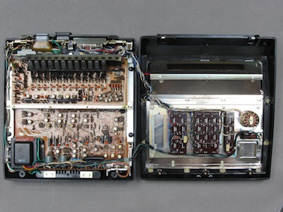
Case opened. The power supply is at the front of the lower case half. The CMU service connector is visible at the rear-right of the lower case half. Bottom of the magnetic-reed switch keyboard seen mounted on the top half of the case. |
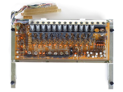
Upper board. Master clock, bit and digit timing counters, numeral decoder, and Nixie display with drivers. |
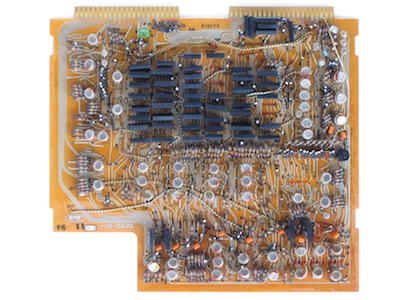
Lower board. The main logic board. The black rectangular modules are packages of 4 diodes making up many of the logic gates of the machine. |
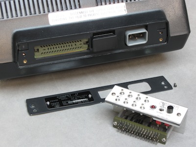
A simple Controller/Monitor Unit (CMU) can be plugged into a service connector at the rear of the calculator, the connector being accessed by removing the label-plate. This CMU, as well as those for other calculators, were constructed after reverse-engineering the calculators, and then assessing what the otherwise-unknown connector on the machines could be used for. The CMU schematic is included in the EEC schematic for the respective calculator. The terminal pins present some useful test points for scoping. The toggle switch selects normal or manual operation. Set to manual, the calculator stops after every major state cycle. The state of the machine can then be inspected, via the display and/or scoping. The push-button continues processing for another state cycle. For example in multiplication, the sub-operations of addition and shifting can be stepped through one at a time. |
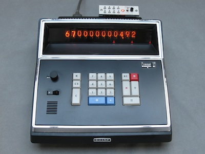
The CMU in operation with the calculator. The calculator is part way through the multiplication 567*123 (note the illuminated BUSY LED on the CMU). The multiplier (567) has been shifted to the upper end of the display register and the 5 shifted into a further, unseen, 4 bits of register, where it is being decremented while controlling additions of the multiplicand (123). The multiplicand has been transferred to another register. The product is building in the lower digits of the display register, here the 4th addition of the multiplicand, out of the 5 for this digit of the multiplier, has just been performed: 4*123=492. Note the decimal point position. The DP register is being used as a primary-loop counter for the multiplication algorithm, the 2 DP positions correspond to the 2 digits of the multiplier (67) which remain to be processed. |
| 810591T | |
| 1968 (transistors stamped with 8K, capacitor with 6749) | |
| 10 Jul 2000 | |
| Polsons Office Supply. | |
| Minor scratches, functional. | |
| Fully functional (Jul 2000). |
| 11 Jul 2000 | |
| Cleaned. |
| 26 Jul 2000 | |
| Short removed from between 4th and 5th 300K resistors (manufacturing flaw). |
| 26 Jul 2000 | |
| Burned out multiply and divide lamps replaced with LEDs and 900 ohm (1.8K/2) resistors in common ground lead. |
| 29 Oct 2004 | |
| Controller/Monitor Unit constructed. Some changes to schematic regarding the remote connector and keyboard. |
| 29 Oct 2004 | |
| TO DO: Simulation should be updated to reflect change of BUSY to IDLE, and P-cycle generation. |
|
Sharp Compet 17
Calculators | Integrated Circuits | Displays | Simulations EEC |
bhilpert |