| bh |
A Solid-State
Hammarlund SP-600 |
|
 By the late 1960s most of the radio industry had made the transition to solid-state designs.
Simple consumer tube radios were headed for the dump,
more substantial and higher-end tube radios were headed for surplus and obsolescence.
Field-effect transistors had been developed in the mid-1960s and were now becoming available and popular.
With FET characteristics being more akin to vacuum tubes than are bipolar transistors (high input impedance, voltage sensing rather than current), interest arose in converting higher-end tube radios to solid-state.
Some articles were written about the topic in ham magazines (some refs below).
By the late 1960s most of the radio industry had made the transition to solid-state designs.
Simple consumer tube radios were headed for the dump,
more substantial and higher-end tube radios were headed for surplus and obsolescence.
Field-effect transistors had been developed in the mid-1960s and were now becoming available and popular.
With FET characteristics being more akin to vacuum tubes than are bipolar transistors (high input impedance, voltage sensing rather than current), interest arose in converting higher-end tube radios to solid-state.
Some articles were written about the topic in ham magazines (some refs below).
The usual idea for such a conversion was to take the tuning infrastructure of the original receiver - which in a higher-end model would be where the value lay - and replace the active electronics with solid-state, while having the chassis and other physical elements such as knobs, switches, pots, etc. to base the reincarnated receiver on.
An appealing idea in principal, although it could take a fair amount of re-design and construction effort.
It wasn't the sort of task which would be worthwhile commercially,
but for hams and short-wave listeners it might be an economic route to a better receiver, either by getting a good tube receiver at reduced price or modernising an already-owned one.
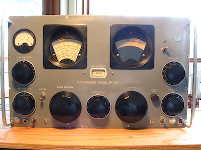
The Hammarlund SP-600 was a higher-end, 20-tube, general-coverage broadcast and short-wave receiver (0.54-54MHz), introduced in the early 1950s.
It was used by the military and commercially into the 60s.
While it is electronically a conventional superhet, with dual-conversion on the higher bands, it had a high quality front-end tuning and band-selection system and selectable-bandwith IF strip.
As such, it could hold some appeal for conversion to solid-state.
This brings us to the unit presented here, which indeed underwent such a transformation.
The FET transistors, other components and design aspects used suggest the conversion was probably done around the early-70s.
It appears it was originally manufactured in its tube incarnation in 1952, based on "6-52" stamped on the 3.5 MHz 2nd-converter crystal.
I like to call it the SSSP-600, for Solid-State SP-600 of course.
A friend purchased this receiver in what was reportedly a well-contested auction.
It worked for awhile after he acquired it but it eventually quit, and he brought it to me with hopes of repair.
Of course there was no schematic or documentation of the conversion.
The conversion effort may have been laudable, but the implementation was - shall we say - a little rough.
There were re-used tube-era components and wiring, a mixture of point-to-point transistor construction alongside scrap PCBs cut up and modified for use in the conversion,
floating solder joints, bits of circuitry that made no electrical or functional sense, the meter had not been wired in, and so on, all on a chassis showing 60+ years of accumulated grime.
We decided that rather than patch a repair, the unit would be reverse engineered,
then the electronics stripped out and rebuilt while correcting and perhaps attempting to improve aspects of the design.
So this unit is now on its third electronics incarnation.
I went into this project blind inasmuch as I had no direct experience with how well it had been performing in its first solid-state incarnation, nor with using an SP-600 in tube form, and thus little to judge against while bringing it back into operation.
With it now operating, just from hands-on experience it seems impressive.
The tuning and selectivity performance I expect are compatible with the tube incarnation and I'm guessing the sensitivity and SNR are an improvement over the tube version.
It would be interesting to set it up with some proper measurement equipment to measure specs like the SNR.
There do remain some bugs such as some spurious oscillations on the high bands, and further design improvements which could be considered.
As a last modification the incandescent dial lamps were swapped out for modern white LEDs, they do make the dial much brighter, and there is no longer anything in the unit to burn out.
It is a novel experience, switching a giant tube-era boat-anchor on and getting instant-on solid-state performance.
|
CONTENTS (this page):
|
SUB-PAGES:
|
EXTERNAL LINKS & REFERENCES:
- SP-600 rebuild at Radio Boulevard site
- "MOSFETs for Tubes", article in QST magazine, 1969 Dec.
"Substitutions in the Old Receiver"
- "Synthesing Vacuum Tubes", article in QEX magazine, 1997 Aug.
"Put that old tube-type receiver back to work by replacing the burnt-out tubes with JFET circuits"
|
The First Solid-State Conversion
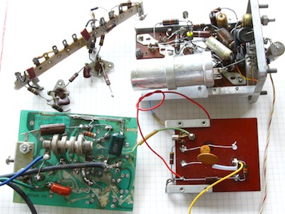
Some portions of circuitry removed during deconstruction of the first conversion.
|
The first conversion performed a near 1-to-1 substitution of transistors for tubes in the RF and IF signal paths.
Most of those transistors are FETs although a few bipolars are present.
The 1st-mixer tube becomes a FET and bipolar in cascode arrangement.
The audio was replaced with a discrete multi-transistor transformer-less arrangement.
A number of other bipolars were added beyond the tube complement.
A total of 8 FETs and around 30 bipolars were used (a lot of the bipolars were in the discrete regulated power supply module and audio amplifier).
No ICs were used in this first conversion, one of the indicators suggesting it was done in the late-60s / early-70s.
Between the 8 FETs, there were 5 different types (!).
Most of them were JFETs, but the 1st RF stage was a single-gate MOSFET and the 2nd RF stage a dual-gate MOSFET with the 2nd gate not being functionally used.
Some functionality of the tube design was left out, e.g. the noise limiter, the fixed-frequency section.
A 100KHz crystal calibrator was added.
Another oddity about this unit is the rack-mount flanges of the front panel had been cut off and carrying handles added.
A case to enclose the other five sides was made out of sheet aluminum panels with hundreds of holes drilled in them.
Perhaps these case alterations were made during its tube incarnation
as the holes for ventilation were quite unnecessary for the transistor version, now they just let dust in.
The Second Solid-State Conversion
In doing the second SS conversion, beyond cleaning up the implementation,
objectives were to eliminate non-functional or incorrect circuitry,
fix some of the design oddities, and bring greater consistency to the design.
It is largely a reimplementation of the first conversion with a few design improvements,
not an attempt at a full design-from-scratch.
The 5 different FET types have been reduced to 2, and could be reduced further to 1, all JFETs.
The main point was to get the 4 stages that are gain-controlled via variable bias from a single source (AVC/RF-gain)
to all be the same type so they would have a similar bias-response characteristic.
In the first conversion, 3 different FET types were under AVC/RF-gain control.
The transistor complement is now 7 JFETs, 9 bipolars, and 3 ICs (2 voltage regulators and an integrated audio amp).
As could be expected, there is now a lot of empty space in the chassis compared to the tube incarnation.
The distance between elements such as IF transformers results in several small boards being distributed around the chassis to help avoid having long RF signal wires running to a single board.
With that said, the power-supply/audio board could have been integrated with the detector/AVC board.
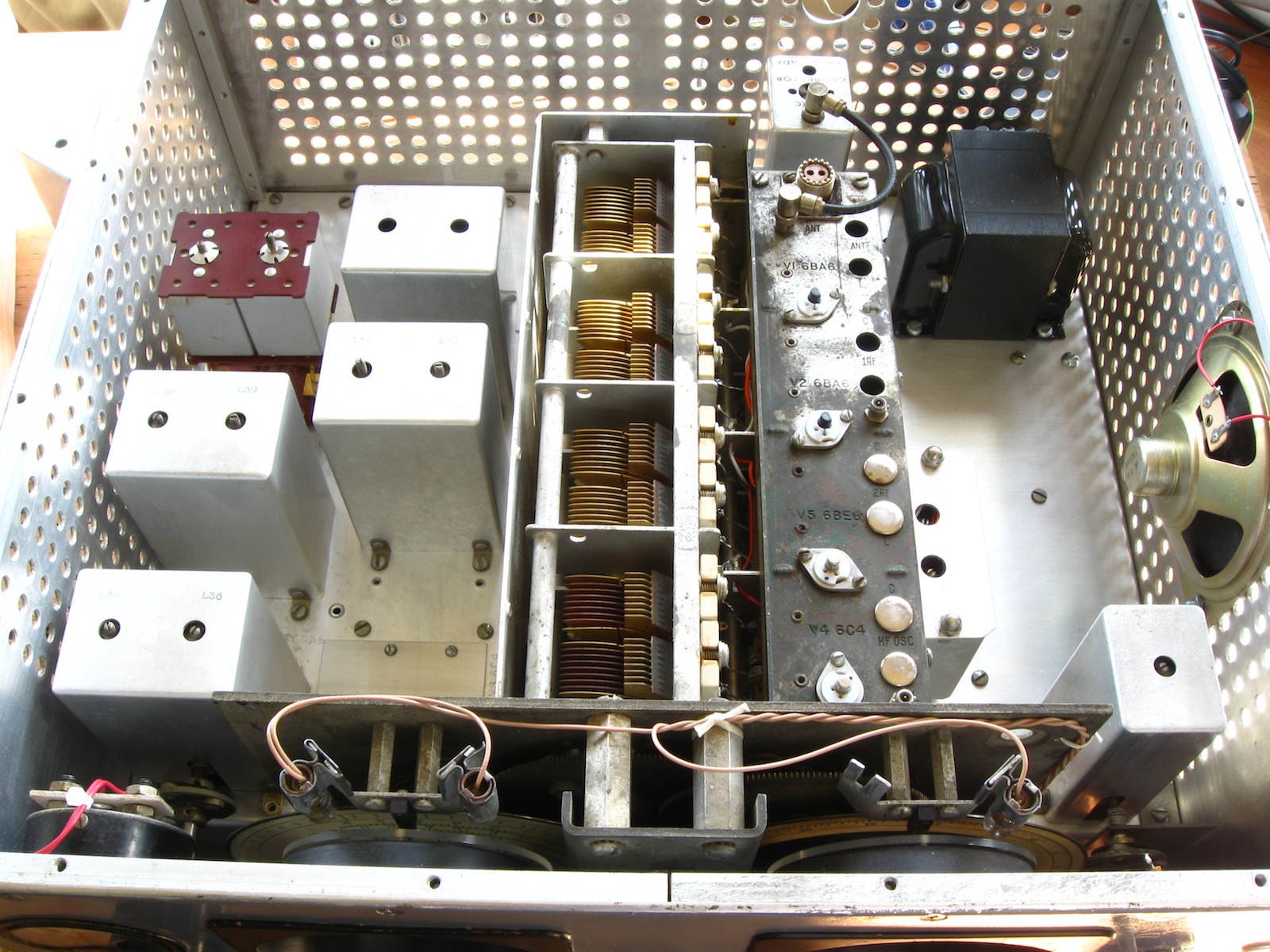
For the front panel, the wiring has been arranged so that all connections to the main chassis transfer on one side, to allow the front panel to swing open for access.
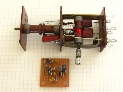
In the photos, the top cover on the front end has been removed, displaying the large 8-section tuning cap.
Front End
Aside from substituting some of the FETs, the front end was left much as it was from the first conversion.
It's point-to-point wiring with some floating solder connections.
If this were to be redone, the floating connections should be eliminated.
The 4 tube sockets had been replaced with transistor sockets for FETs.
From left-to-right in the photos are the antenna input, 1st RF stage, 2nd RF stage, mixer and HFO.
In addition to the 4 socketed FETs, 3 bipolars are inside.
One of these works with the mixer FET to form the cascode mixer stage.
Another is an HFO buffer connected to a mini-coax socket, this is useful for feeding a frequency counter during alignment.
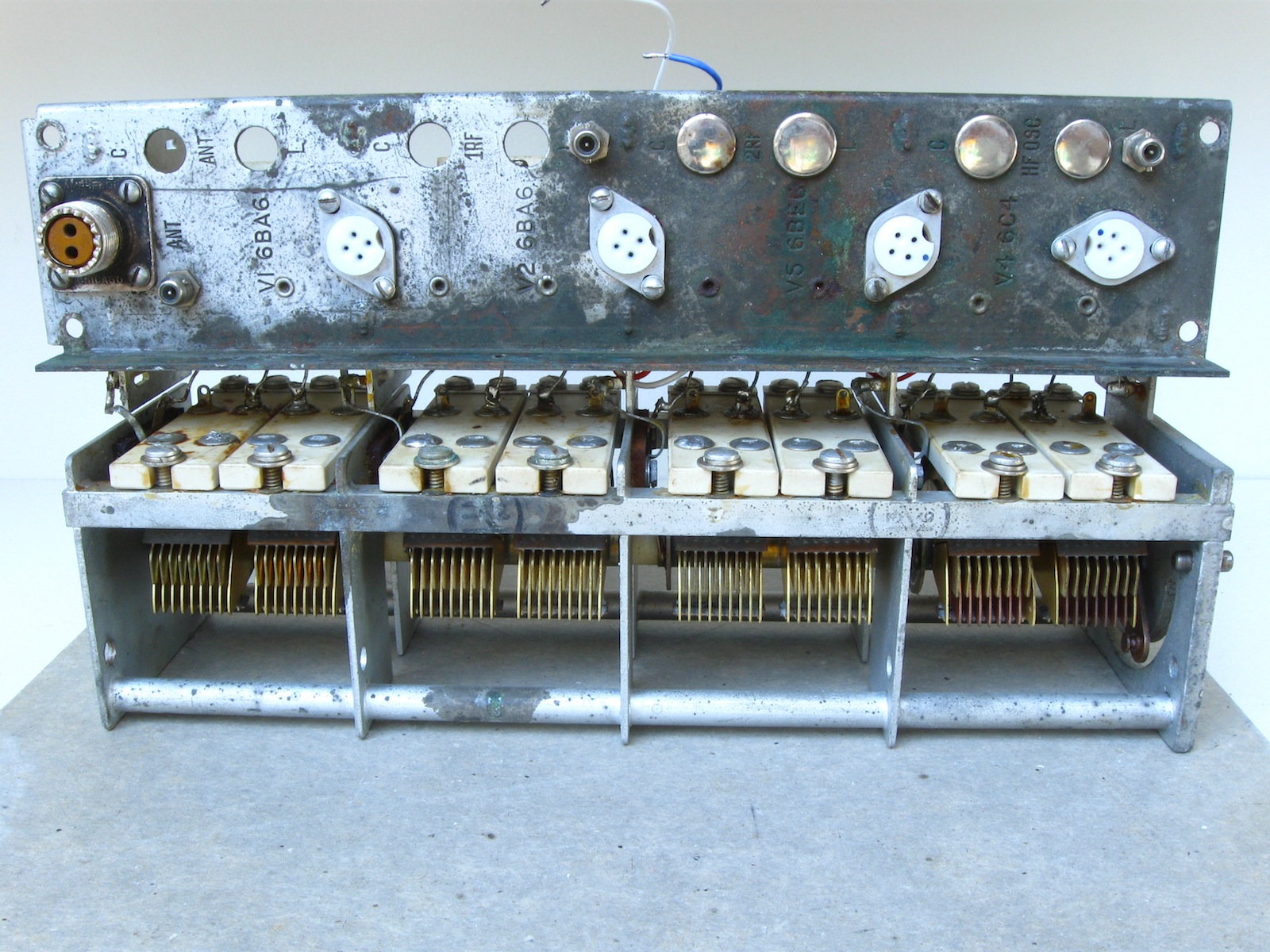
The SP-600 manual documents removing the tuning cap and electronics strip of the front end as separated units.
It is possible with some finicky maneuvering to remove these as one unit, without unsoldering them from each other.
The key in this is to detach the 2-inch mounting bar at the rear of the electronics strip from both the electronics strip and the front-end enclosure.
ATTN: In removing and reassembling the front end, be sure to disengage the band coils and otherwise observe care not to mash the band-switch contacts.
Also note the presence of a spacing washer on the tuning-cap mounting screw at the front, situated between the tuning mechanism plate and the tuning-cap frame.
Tightening the screw in the absence of the washer will bend the tuning-cap frame.
2nd Converter
 The 2nd-converter board contains the 3.5 MHz crystal oscillator and mixer for dual-conversion on the upper bands (above 7.4 MHz), as well as an IF buffer-switch for the lower bands (below 7.4 MHz).
The switching of the IF paths for single/dual conversion is incorporated on this board.
In the first SS conversion, this switching was performed by an electro-mechanical relay.
It is now accomplished electronically via diode switching.
The 2nd converter mixer and lo-band buffer transistors are set up with a biasing network that presents a hard-negative bias to the according transistor when it is to be off, to shut down that signal path.
In theory, the collectors of the transistors could be wired directly together for the output, however even with a transistor hard off there is enough signal coupled from the base to collector to be quite noticeable.
A diode which also switches on/off with the biasing is added in series with each collector to provide greater isolation, the anodes of the diodes then being connected together as the common output, for input to the 455 KHz IF strip.
This board is normally covered by an aluminum can for shielding.
IF Amplifiers
The two small boards beneath the long rotary switch are the two 455 KHz IF amplifier stages.
The rotary switch is for IF bandwidth selection.
Detectors & AVC
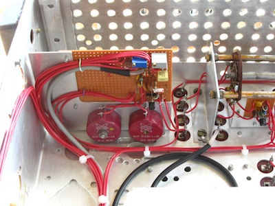 The detector arrangement is a little unusual, but is essentially replicating that of the tube version.
A buffer after the last IF transformer capacitively drives two shunt rectifiers, one for the AM signal and one for AVC.
The detector arrangement is a little unusual, but is essentially replicating that of the tube version.
A buffer after the last IF transformer capacitively drives two shunt rectifiers, one for the AM signal and one for AVC.
The board shown here contains the detector driver, the two detectors, associated filters, and voltage dividers for AVC and the meter.
The grey trimmer pot is for the AVC level, the blue trimmer is for meter deflection.
In the first conversion the AVC was a bizarrely-complex 4-transistor arrangement with one transistor apparently reverse-biased.
It wasn't clear how the circuit was functioning, or whether it did to any great benefit.
It has been replaced with a simple but quite effective passive arrangement.
BFO
 One design aspect that differed in the first SS conversion from the tube design was the BFO.
The simple BFO-injection into the IF/detector signal path of the tube version was replaced with a discrete differential-amp.
It looks sophisticated but I don't think it's actually a product detector.
It seems to be relying simply on a mixing action and non-linearity around the common emitters of the 'long-tail pair', which actually has a rather short tail.
While it does work for SSB, and a beat can be tuned in and nulled with AM signals, shutting down the oscillator still leaves the AM signal just as it was with the nulled beat.
It looks like it may have been a transistorised version of a tube circuit described in CQ magazine, 1956 Nov.
One design aspect that differed in the first SS conversion from the tube design was the BFO.
The simple BFO-injection into the IF/detector signal path of the tube version was replaced with a discrete differential-amp.
It looks sophisticated but I don't think it's actually a product detector.
It seems to be relying simply on a mixing action and non-linearity around the common emitters of the 'long-tail pair', which actually has a rather short tail.
While it does work for SSB, and a beat can be tuned in and nulled with AM signals, shutting down the oscillator still leaves the AM signal just as it was with the nulled beat.
It looks like it may have been a transistorised version of a tube circuit described in CQ magazine, 1956 Nov.
The BFO tank coil was a bit of a mess, with two leads broken.
One of those was broken at the base of the winding, so it had to be rewound.
Not very pretty but it works well enough to get the oscillator going within range.
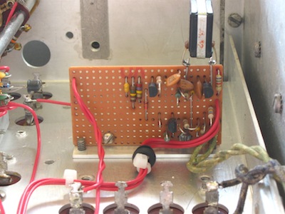
Power Supply & Audio
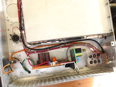 The intention for the audio here had been to use a TDA2030A integrated amp IC in dual-supply configuration,
as the power supply was going to be dual supply to provide negative bias for the FETs anyways.
I managed to blow two 2030 ICs and a speaker during the construction process, partly due to the lack of the cap in the output to block DC.
The 2030 specs claim it has short-circuit protection but it didn't do much for me.
I decided to revert to the more robust single-supply with blocking cap configuration, and instead of rewiring the circuit just mounted one
of those ubiquitous preconstructed power amp modules which use the 2030, which my friend had obtained.
The intention for the audio here had been to use a TDA2030A integrated amp IC in dual-supply configuration,
as the power supply was going to be dual supply to provide negative bias for the FETs anyways.
I managed to blow two 2030 ICs and a speaker during the construction process, partly due to the lack of the cap in the output to block DC.
The 2030 specs claim it has short-circuit protection but it didn't do much for me.
I decided to revert to the more robust single-supply with blocking cap configuration, and instead of rewiring the circuit just mounted one
of those ubiquitous preconstructed power amp modules which use the 2030, which my friend had obtained.
The installed BFO board is visible on the right side of the photo.
The octal tube socket is for the 100KHz crystal calibrator plug-in module.
Front Panel Controls & Operation
 Some of the switch locations for unimplemented functions have been repurposed.
- POWER Switch (was XTAL FREQ delta):
The power switch is now a toggle in the upper right where the fixed-frequency controls were originally,
rather than the original secondary function of the RF GAIN control knob.
- Meter:
The meter monitors the voltage level coming out of the AM detector.
It is internally set such that "80" is about the maximum deflection one should observe for idle carrier.
Modulation peaks may push the deflection beyond this but as the level approaches "100", the detector may be overdriven and start distorting and clipping.
Further beyond 100 the detector will be driven into saturation, leaving little-to-no modulation signal information getting through.
The original meter scale units are meaningless here.
- AVC/MAN Switch & RF GAIN:
The AVC/MAN switch selects AVC versus MANUAL control of the RF and IF gain.
In MANUAL mode, the RF GAIN knob adjusts the gain.
In this mode, the RF GAIN is typically adjusted for a meter deflection approaching 80.
In AVC mode, AVC circuitry provides primary control of the gain, while the RF GAIN knob presents a lesser degree of influence.
In this mode, normal operation is to have the RF GAIN control at maximum, the gain can then be backed off if desired.
The AVC is internally set to target a strong station giving meter deflection around 80 when the RF GAIN control is at maximum.
- SPEAKER Switch (was LIMITER Switch):
There is no noise limiter in the conversion, the original LIMITER switch location is repurposed as an ON/OFF switch for an internal speaker.
- CRYSTAL CALIBRATOR Switch (was METER Switch):
The original METER switch location is repurposed as an ON/OFF switch for an added 100KHz crystal calibrator.
Bugs, Anomalies, Further Design Considerations
-
Investigate: There are some spurious oscillations in the high bands.
Peaking 2nd converter coils L33/34 can exacerbate this.
Could try reducing the gain of the hi-band mixer.
-
Investigate: There can be some audio distortion on strong stations. This can be alleviated by backing off the RF Gain.
Might be just that the AVC level is set too high.
-
Investigate: Occasionally switching selectivity between 3-8-13 shows more variability in main-channel level than normal.
Not sure whether this is a hardware intermittent or something to do with spectrum noise proximity.
-
Design: Replace the few bipolars in the RF/IF signal path fed by tuned circuits with FETs.
Also bring those stages under AVC/gain control.
-
Design: Replace the HFO and 1st mixer FETs with the same type as the other FETs (or vice versa), to get the FET types down to 1.
This may require some adjustment of the biasing and perhaps accounting for differing gate C for the HFO.
-
Design: Provide for the meter to be switched to monitor the gain level as well as the current detector level.
 By the late 1960s most of the radio industry had made the transition to solid-state designs.
Simple consumer tube radios were headed for the dump,
more substantial and higher-end tube radios were headed for surplus and obsolescence.
Field-effect transistors had been developed in the mid-1960s and were now becoming available and popular.
With FET characteristics being more akin to vacuum tubes than are bipolar transistors (high input impedance, voltage sensing rather than current), interest arose in converting higher-end tube radios to solid-state.
Some articles were written about the topic in ham magazines (some refs below).
By the late 1960s most of the radio industry had made the transition to solid-state designs.
Simple consumer tube radios were headed for the dump,
more substantial and higher-end tube radios were headed for surplus and obsolescence.
Field-effect transistors had been developed in the mid-1960s and were now becoming available and popular.
With FET characteristics being more akin to vacuum tubes than are bipolar transistors (high input impedance, voltage sensing rather than current), interest arose in converting higher-end tube radios to solid-state.
Some articles were written about the topic in ham magazines (some refs below).