 Alignment procedures are covered in the RA-117 manufacturer's manual.
Presented here are some additional comments and hints gained from the experience of rebuilding several RA-117s.
Alignment procedures are covered in the RA-117 manufacturer's manual.
Presented here are some additional comments and hints gained from the experience of rebuilding several RA-117s.
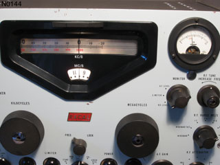
The photo at right shows a unit tuned to WWV at 10MHz.
Broadly speaking, there are two major aspects to realigning the RA-117, that of dial/frequency calibration and that of aligning the various RF/IF filters.
The first consideration to be made is that most of the alignment may well be just fine - even after extensive component replacement and rebuilding - if the primary resonance components in the various sections have not been altered.
There are, of course, two main aspects to frequency/dial calibration:
- 1st VFO: Absolute frequency is easy, linearity is not difficult.
- 2nd VFO: Absolute frequency is easy, high linearity and accurate tracking may be difficult.
RF and IF filters:
- RF front end: procedure is fairly typical.
- Wadley loop bandpass filters: special equipment, probably don't need to be touched.
- 2-3 MHz IF filter: manual says don't touch it.
- 1.6MHz IF filter.
- IF bandwidth filters.
- 100KHz IF filter: typical IF alignment procedure.
Other:
In addition to the above there are a couple of traps and such.
The 1st VFO can be calibrated in place by pulling V4 and feeding a frequency counter from pin 1.
- With the MC dial set to 0, the VFO should produce 40.5 MHz.
- With the MC dial set to 29, the VFO should produce 69.5 MHz.
It is not too difficult to get the tracking quite accurate by alternately adjusting L36 for 40.5 MHz and C77 for 69.5 MHz.
While it is reasonably easy to use the crystal calibrator to set the 2nd VFO dial pointer at any 100KHz point along the film scale, part of the fun of the RA-117 is achieving a high degree of linearity across the entire dial from 0 to 1000 KHz.
If one is lucky, this will not have been upset since the unit left the factory.
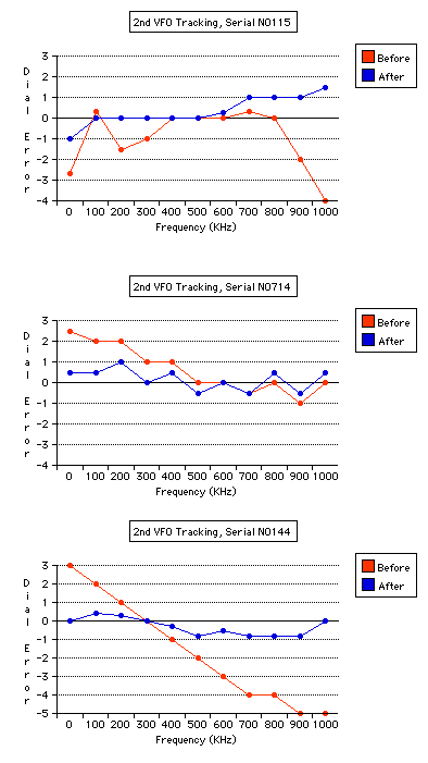
The graphs show the improvement achieved on three units.
After the initial rebuild and reassembly of the units, and some realignment to just get the frequencies reasonably correct, the tracking was as shown with the red lines.
Unit N0115 was not too bad except at the end points, with an overall deviation of less than 5 KHz.
Unit N0714 had a gradual error over the range, but less than 3.5 KHz overall deviation.
The blue lines show the results after some vane tweaking and repositioning of the rotor: much better in both units,
in N0714 an overall deviation of about 1.5 KHz, so less than ± 1 KHz or within one scale mark on either side of target.
Unit N0144 had quite of bit of error, but the error was quite linear. Minimal adjustment of the proportion of base capacitance brought the error down to less than ± 1 KHz. No vane tweaking was required.
In aligning the 2nd VFO there are three objectives to be achieved:
- Linearity: a given change of the dial at any point on the dial should produce the same change in frequency (turning the dial through a 100KHz span should produce 100KHz of change, whether that span is, for example, 0-100, 400-500 or 900-1000).
- Spread: even if linear across the dial, a given change in the dial must produce the desired change in frequency (i.e.: turning the dial through a 100KHz span should produce 100KHz of frequency change, not 99 or 102 KHz).
- Absolute frequency: the VFO output should be 4.600 MHz at a dial reading of 0, and 3.600 MHz at 1000.
The variables that one has to play with to achieve the above objectives:
- Trimmer (base capacitance).
- Rotor positioning (base capacitance):
Loosening the two screws of the clamp on the gear bushing on the variable capacitor shaft permits the capacitor plates to be rotated independant of the drive and scale.
Requires removal of the left side panel.
- Vane tweaking: the vanes are made of a fairly stiff metal with silver plating.
They are quite difficult to bend and care must be taken not to scratch the plating.
- Inductor adjustment: the manual says don't touch it. I take the writer's word on this, every effort should be made to avoid messing with the inductor and presumably it shouldn't be necessary except in exceptional circumstances.
Some comments on technique:
- A frequency counter can be fed from SK304 to measure the 2nd VFO output, but it may pull the frequency off by a couple of KHz.
- If the spread is too great in a particular 100KHz span (100KHz of oscillator frequency spread requires more than 100KHz of dial - the oscillator is not changing quickly enough), then more C must be added by bending a rotor vane towards the stator.
- Base C can affect the spread. More base C will reduce the ratio of the maximum capacitance to the lowest capacitance, hence reducing the total change in frequency.
- Trying to achieve linearity at the low end (0 KHz) of the dial through vane-tweaking is problematic in that it will also change the capacitance and hence tracking for the rest of the dial spread.
If it is necessary to do vane-tweaking at the low end of the dial (vanes open), be prepared to iterate over the rest of the dial in the process.
In achieving linearity, it may be best to start at the low end of the dial, using path-of-least-effort techniques, and proceed up the scale, hopefully leaving vane-tweaking till the high end (vanes meshed).
|
Aligning the Crystal Calibrator |
While doing an instrument recalibration of the calibrator it was found that peaking the coils with the instruments may not bring the unit to function.
The coils may still be far enough off to prohibit the mixing loop from automatically starting.
A test lead on the plate or grid of the tubes to pull the frequency may set the unit into or out of operation.
Fine adjustment of the coils may be necessary to find the operating area for the unit.
-
The manual does not describe exactly how to align C108 (balance/null on the 37.5 MHz amp).
During alignment of one unit, a slight whistle was noticed when the antenna attenuator was switched in.
Trimming C108 under these conditions reduced the whistle.
-
Quick 40 MHz BPF measurements: Tuning VFO1 down to 40MHz (just below 0) (counter fed from TP2) shows ~ 4.7 VPP on TP2.
At the output of the BPF (midpoint tap on L50) ~ 5.2 VPP is observed.
 Alignment procedures are covered in the RA-117 manufacturer's manual.
Presented here are some additional comments and hints gained from the experience of rebuilding several RA-117s.
Alignment procedures are covered in the RA-117 manufacturer's manual.
Presented here are some additional comments and hints gained from the experience of rebuilding several RA-117s.