 The RA-17 & RA-117 receivers are based on the Wadley loop tuning system, making them quite complex for shortwave receivers.
24 tubes are present in the RA-17, 26 tubes in the RA-117.
The RA-17 is a triple conversion receiver, the RA-117 has 4 heterodyne conversion stages.
The nature of the Wadley loop, involving a harmonic generator and signals at numerous frequencies, results in the need for extensive shielding between sections and RF filtering of B+ and filament supplies.
Although the receivers only tune up to 30MHz, frequencies up to near 70MHz (low VHF) are present, particularly around the 1st VFO sub-chassis.
The RA-17 & RA-117 receivers are based on the Wadley loop tuning system, making them quite complex for shortwave receivers.
24 tubes are present in the RA-17, 26 tubes in the RA-117.
The RA-17 is a triple conversion receiver, the RA-117 has 4 heterodyne conversion stages.
The nature of the Wadley loop, involving a harmonic generator and signals at numerous frequencies, results in the need for extensive shielding between sections and RF filtering of B+ and filament supplies.
Although the receivers only tune up to 30MHz, frequencies up to near 70MHz (low VHF) are present, particularly around the 1st VFO sub-chassis.
Beyond the Wadley Loop, the receivers are constructed with the ruggedness, stability and additional features of a premium receiver, such as selectable-bandwidth IF, with crystal filters on the narrowest ranges.
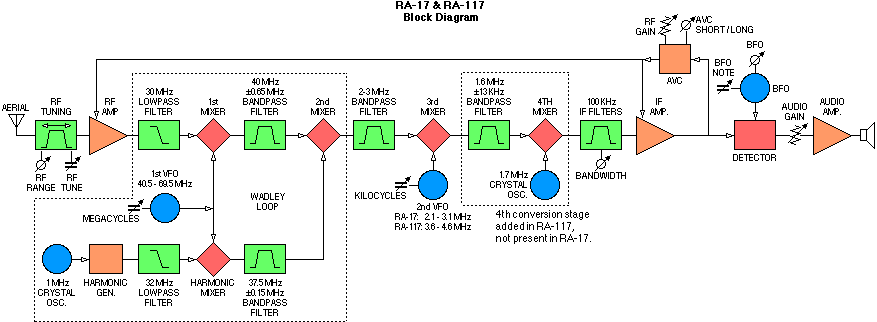
A block diagram of the RA-17 and RA-117 is shown below, followed by some description of the Wadley Loop and other aspects of the receivers.
The block diagram shown here is a slightly simplified version,
a more complete block diagram is presented with the RA-117 schematic.
The Wadley Loop
In a superheterodyne receiver, for a given channel bandwidth, oscillator stability becomes more critical as the received frequency increases.
For example, it is not too difficult to produce a stable receiver for the standard AM broadcast band, where a channel bandwidth of 10 KHz is 1% of the signal at 1 MHz.
At 10 MHz however, a 10 KHz channel is only 0.1% of the signal, requiring oscillators and circuitry of considerably improved precision and stability to discern such a channel.
The Wadley Loop addresses these issues of tuning precision and stability.
The objective of the Wadley Loop is to shift a portion of spectrum from a high frequency down to a lower frequency.
The shifting is accomplished relative to a crystal-controlled reference to obtain the precision and stability.
At the lower frequency the shifted spectrum can be tuned by a high-quality but conventional superhet section.
In most or all receivers utilising the Wadley Loop, the portions of spectrum shifted were 1 MHz wide.
This was convenient for the user as one dial would tune the 'MHz part' of the signal, while a second dial would tune the 'KHz part'.
| Wadley Loop Mixing Equation |
IF2 = (VFO1-SIG) - (VFO1-nX)
    = VFO1 - SIG - VFO1 + nX
    = nX - SIG

IF2  = 2nd IF frequency
VFO1 = 1st VFO frequency
SIG  = RF input frequency
nX   = some integral multiple of 1 MHz
|
|
|
The Wadley Loop is seen in the first half of the block diagram above.
In the RA-17 and 117 the process begins with the production of a comb of 1 MHz markers spanning 1 to 32 MHz, accomplished by a 1 MHz crystal oscillator feeding a harmonic generator.
The output of the manually-tuned 1st VFO is mixed with both the RF input and this comb of 1 MHz markers.
The output of the RF mixer is fed to an IF filter with a bandpass a little wider than 1 MHz and centred on 40 MHz.
The output from the harmonics mixer is fed to a fairly narrow bandpass filter tuned to 37.5 MHz.
As the 1st VFO is tuned, at particular frequencies 1 MHz apart, the output of the harmonic mixer will make it through the 37.5 MHz filter.
This is mixed with the 1 MHz wide RF spectrum coming out of the 40 MHz filter to produce a 2nd IF signal of 40-37.5=2.5 MHz.
The resultant mixing equation is shown at the right.
The key to the Wadley Loop is the mixing is arranged in such a manner that the 1st VFO is both an addend and subtrahend in the net equation and so eliminated:
1st VFO drift within the limits of the bandpass of the 37.5 MHz filter is cancelled out.
Other receivers implementing the Wadley Loop may use different frequencies internally for the oscillators, IF stages, bandpass filters, etc.
After the Wadley Loop
The output of the Wadley loop (the 2nd IF signal) is fed to the second half of the system,
a superhet design which tunes across the 1 MHz spectrum of the 2.5 MHz 2nd IF, seen in the second half of the block diagram.
In the RA-117, yet another conversion stage is present, involving the 1.6 MHz IF filter, 1.7 MHz crystal oscillator and 4th mixer, making it a quad conversion receiver.
This is in contrast to the earlier RA-17, in which the 2nd VFO and 3rd mixer produce the final 100KHz IF.
This is the primary distinction between the RA-17 and RA-117.
The final IF stage of 100 KHz incorporates a switchable bandwidth filter providing 6 bandwidth selections from 100 Hz to 13 KHz, followed, conventionally, by a BFO, detector, AVC, noise limiter and audio stages.
Tuning Examples
| Tuning Examples |
| |
Equation |
Ex.1a |
Ex.1b |
Ex.1c |
Ex.2a |
Ex.2b |
Ex.3 |
| MHz Dial |
MD |
5 |
5 |
5 |
4.85 |
5.15 |
0 |
| KHz Dial |
KD |
0 |
1 |
999 |
0 |
0 |
690 |
| Signal Tuned |
SIG |
5 |
5.001 |
5.999 |
5 |
5 |
0.69 |
| 1st VFO |
VFO1 = 40.5 + MD |
45.5 |
45.5 |
45.5 |
45.35 |
45.65 |
40.5 |
| 1st IF |
IF1 = VFO1 - SIG |
40.5 |
40.499 |
39.501 |
41.35 |
40.65 |
39.81 |
| Harmonic Amp |
HA = VFO1 - (INT(MD)+3) |
37.5 |
37.5 |
37.5 |
38.35 |
37.65 |
37.5 |
| 2nd IF |
IF2 = IF1 - HA |
3 |
2.999 |
2.001 |
3 |
3 |
2.31 |
| 2nd VFO |
VFO2 = 4.6 - KD |
4.6 |
4.599 |
3.601 |
4.6 |
4.6 |
3.91 |
| 3rd IF |
IF3 = VFO2 - IF2 |
1.6 |
1.6 |
1.6 |
1.6 |
1.6 |
1.6 |
| 4th IF |
IF4 = 1.7 - IF3 |
0.1 |
0.1 |
0.1 |
0.1 |
0.1 |
0.1 |
| All values in MHz except KHz Dial |
|
|
The table to the right presents some tuning examples.
Example 1a shows precise tuning to 5 MHz.
1b and 1c show the extremes of the 1 MHz passband through the Wadley loop and the subsequent KHz tuning within that range by the 2nd VFO.
Examples 2a and 2b show how the 1st VFO frequency can vary without affecting the output from the 2nd mixer.
Example 3 shows the frequencies involved at the low end of the AM broadcast band (0 MHz, so to speak).
Note the inverse frequency span of the 2nd VFO.
The oscillator frequency goes down from 4.6 MHz to 3.6 MHz as the tuned frequency (dial indication) increases from 0 to 1000 KHz.
The 1 MHz spectrum was reversed in the Wadley loop as the signal passband was the subtrahend in the Wadley loop mixing equations.
This matters if one is working on the 2nd VFO: the variable capacitor plates are meshed (high C) at the high end of the tuning scale - the reverse of what is usually encountered in receivers.
Anomalies
The Wadley Loop with the numerous mixing and filtering stages gives rise to some odd behaviour.
Note that, strictly speaking, much of this cannot be regarded as flaws, as the manufacturer specifications only cover the range 1 to 30 MHz.
 The RA-17 & RA-117 receivers are based on the Wadley loop tuning system, making them quite complex for shortwave receivers.
24 tubes are present in the RA-17, 26 tubes in the RA-117.
The RA-17 is a triple conversion receiver, the RA-117 has 4 heterodyne conversion stages.
The nature of the Wadley loop, involving a harmonic generator and signals at numerous frequencies, results in the need for extensive shielding between sections and RF filtering of B+ and filament supplies.
Although the receivers only tune up to 30MHz, frequencies up to near 70MHz (low VHF) are present, particularly around the 1st VFO sub-chassis.
The RA-17 & RA-117 receivers are based on the Wadley loop tuning system, making them quite complex for shortwave receivers.
24 tubes are present in the RA-17, 26 tubes in the RA-117.
The RA-17 is a triple conversion receiver, the RA-117 has 4 heterodyne conversion stages.
The nature of the Wadley loop, involving a harmonic generator and signals at numerous frequencies, results in the need for extensive shielding between sections and RF filtering of B+ and filament supplies.
Although the receivers only tune up to 30MHz, frequencies up to near 70MHz (low VHF) are present, particularly around the 1st VFO sub-chassis.