 Restoring an RA-117 is a long and involved project compared to more-typical shortwave receivers.
Following are some general notes, and some examination of the various sections of the receiver.
Alignment is discussed on a separate page.
Restoring an RA-117 is a long and involved project compared to more-typical shortwave receivers.
Following are some general notes, and some examination of the various sections of the receiver.
Alignment is discussed on a separate page.
|
Restoring an RA-117 is a long and involved project compared to more-typical shortwave receivers.
Following are some general notes, and some examination of the various sections of the receiver.
Alignment is discussed on a separate page.
In the tradeoff between making an assessment of the resistors and deciding which ones to replace versus simply replacing them all, the latter approach may well be preferable.
| Main Chassis |
 Bottom of bare chassis. |
 Bare chassis with components. |
The receivers are based on a large cast-aluminum chassis, with several cast-aluminum sub-chassis mounted onto the main chassis.
As can be seen, the 100KHz IF strip is also removable.
 Ready for final assembly. |
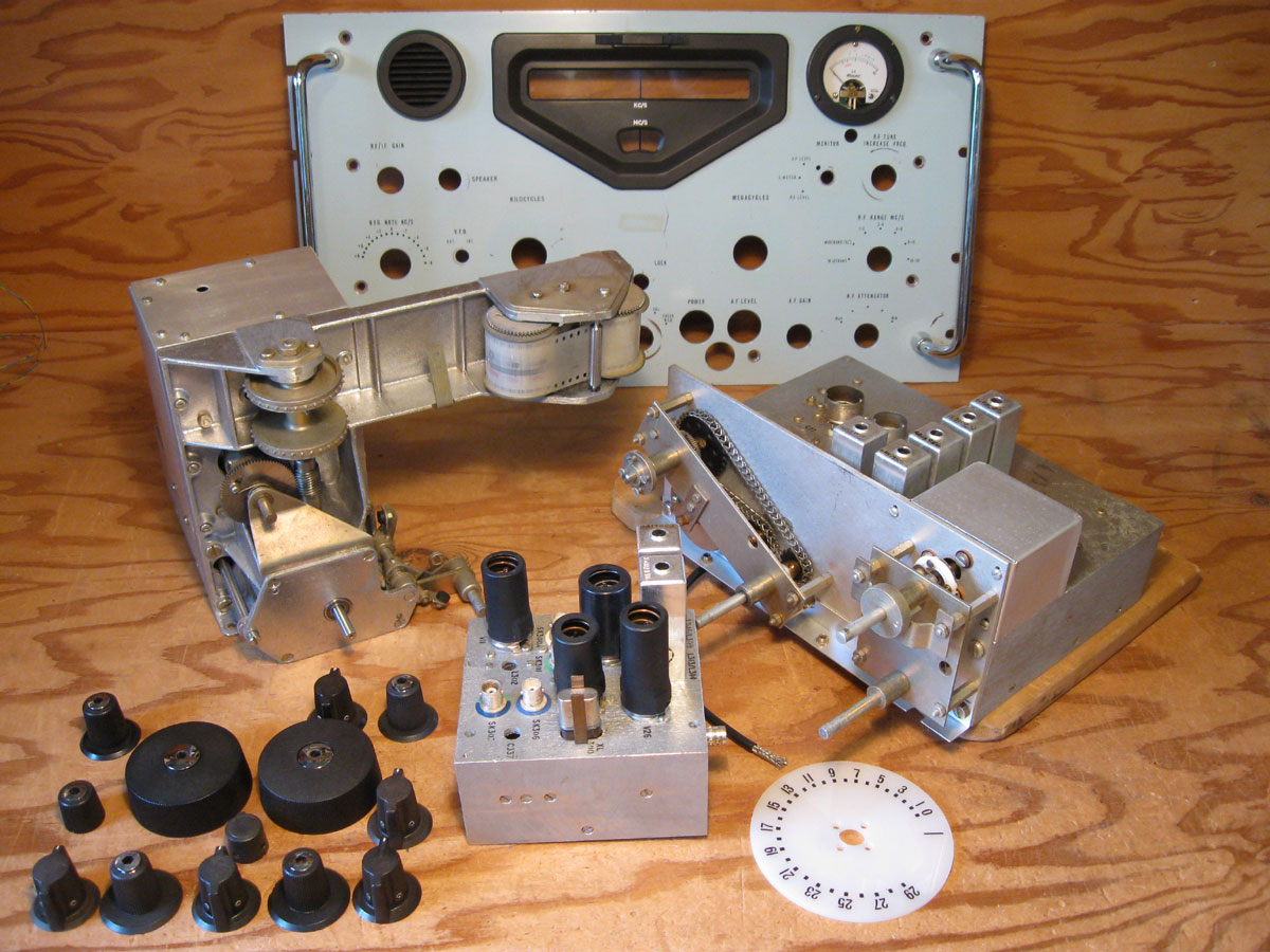 Modules and other bits. |
During any significant rebuild of the main chassis, removing or leaving off the power transformer and choke as well as other modules makes the chassis much easier to maneuver and handle.
Not shown are the side, top and bottom panels.
FRONT |
 REAR |
 LEFT |
 RIGHT |
 BEFORE |
 REBUILT |
System switch: The system switch may look like a typical rotary switch, however it actually has special make-before-break contacts. The system switch controls the main B+ line in the S5.1L section. If this line goes open arcing can result as current is interrupted through the filter choke. The make-before-break contacts are intended to keep a load on the supply as the switch is rotated between positions, in contrast to normal break-before-make contacts which would open the line briefly.
Arc-damaged contacts have nonetheless been observed on one original switch, leading to greater arcing and deterioration as the contact is eaten away and the make-before-break facility is lost.
In one unit the original system switch was missing. Replacing it with a normal break-before-make type (the white-wafer unit seen in the first rebuild here) resulted in significant arcing. It was subsequently replaced again with a proper type.
It is possible to remove the switch and rotate the wafers to provide a 'good' set of contacts on the B+ line and move the bad set to another position where the make-before-break facility is not of consequence, although removing and working around this switch is not easy.
 REBUILT |
 Switch compartment. |
In this instance the circuitry was modified to eliminate two poles on the system switch, so only two wafers (4 poles) are needed, rather than 3 wafers.
 One of the toggle switches dismantled for cleaning and lubrication, showing all the tiny parts involved.
| 1st VFO Subchassis |
 1st VFO Module |
 REBUILT |
 RF compartment, PARTIALLY REBUILT |
 RF Compartment, REBUILT |
 Oscillator compartment, PARTIALLY REBUILT |
 Oscillator Compartment, REBUILT |
 Apparently Meccano wasn't just a child's toy.
The gearing on the 1st VFO actually uses bits of Meccano.
(The Meccano label is readable in the larger version of the photo).
Apparently Meccano wasn't just a child's toy.
The gearing on the 1st VFO actually uses bits of Meccano.
(The Meccano label is readable in the larger version of the photo).
| Harmonics Generation Compartments |
 BEFORE |
 REBUILT |
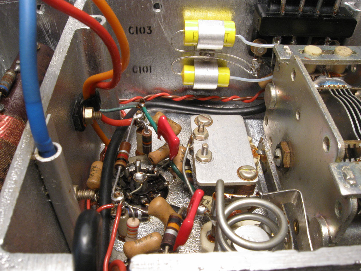
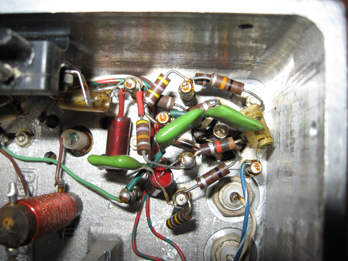
Change: the 4.7K resistor originally mounted between two tabs on the coil is moved below and connected directly to the component board.
The 47K resistor stretching way over to V1 is now mounted in this place and a wire connects over to V1.
 BEFORE |
 REBUILT |
The small aluminum separator panel is best removed for access during the rebuild.
| 2nd Mixer Compartment |
 BEFORE |
 REBUILT |
 BEFORE |
 REBUILT |
Note two 0.001 caps stacked for compactness.
| 2nd VFO Subchassis |
 2nd VFO Module |
 Tuning Compartment |
 BEFORE |
 REBUILT |
In working on one unit, three issues needed to be addressed to get it running freely and smoothly:
|
Electronically, refurbishing the 2nd VFO is quite straightforward.
| 3rd & 4th Mixer Subchassis |
 Ready for assembly. |
 Under assembly. |
 BEFORE |
 REBUILT |
 BEFORE |
 REBUILT |
 BEFORE |
 REBUILT |
| 100 KHz IF & Detector/AVC |
 BEFORE |
 REBUILT |
Note all the missing paper caps in the 'original' photo, these had already been stripped when the receiver was received.
 BEFORE |
 REBUILT |
 Stripped. |
 Components ready for re-assembly. |
 Top/component side. |
 Bottom/wiring side. |
The original IF boards had been broken during the 'de-milling' process. Some reorganisation of the components has been performed so the component ordering does not match the original exactly.
The Power Supply/Audio board is a new design to replace the original point-to-point wiring in that section.
 Amp load, BEFORE. |
 Amp load, REBUILT. |
 BFO, BEFORE. |
 BFO, REBUILT. |
 Forward half, REBUILT. |
 Rear half, REBUILT. |
| Crystal Calibrator Module |
 BEFORE |
 REBUILT |
The unit shown was actually from an RA-17, note the funny coax connector in the picture of the original.
For use in an RA-117 it was rebuilt with a BNC connector.
The little mounting bracket on the end opposite the octal plug also had to be remade as the thumb-screw mounting hole on the 2nd VFO was moved about a quarter of an inch from the RA-17 to RA-117.
 BEFORE |
 REBUILT |
| Power Supply & Audio Compartment |
 BEFORE |
 REBUILT |
 BEFORE |
 REBUILT |
In the instances shown, the compartment was completely stripped and all RC components replaced. The layout was redesigned to clean up some of the wiring. Two redesigns are shown.
The first uses common terminal strips to hold the new axial-lead filter caps and other parts of the power supply, along with a new component board (seen on the left in the photo) to hold the audio cathode-circuit and feedback components. This space was originally occupied by the power supply filter electrolytic capacitors. This arrangement has the benefit of better separating the audio and power supply circuits: the wires to the power supply filter caps do not have to traverse through the audio area.
The second redesign incorporates a new component board holding almost all the smaller RC components of the power supply and audio sections.
 Power resistors. |
 Power resistors, and modern IEC connector. |
In both redesigns of the power supply / audio compartment, to solve the heat problem, the power resistors were moved out of the compartment to the top of the chassis, occupying the space where the rectifier tube was located in the RA-17, an area left empty in the RA-117. Shown are two methods of installing the three power resistors.
Note also the IEC power connector in the one photo.
There is just enough room on the back panel of the chassis between and below the two fuses to install a standard IEC power connector if one is so inclined, to replace the original fixed line cord.
Some may not like such a 'modern' alteration, but I can't stand equipment with dangling power cords.
|
Technical
| Versions
| Rebuild
| Alignment
Racal RA-17 & RA-117 |
bhilpert Apr 2008 |
