| Section or Issue |
RA-17 Earlier |
RA-17 Later |
RA-117 Earlier |
RA-117 Later |
|
Sample serial numbers
|
|
|
N8, N16
|
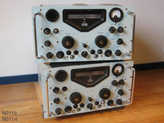
N0115, N0144, N0714
|
|
1.6MHz IF
|
Not present.
The 2-3 MHz IF is mixed with the 2nd VFO to produce the final 100 KHz IF.
The 2-3 MHz IF is a tuned filter involving multiple sections on the KC (2nd VFO) tuning cap.
|
A fourth conversion stage with an IF frequency of 1.6 MHz is inserted between the 2-3 MHz IF stage and 100 KHz IF stage.
This involves the addition of 3 tubes and another small sub-chassis.
The 2-3 MHz IF filter is a fixed bandpass filter.
The 2nd VFO is altered considerably: the frequency span changed, and the variable cap reduced to a single section, for the oscillator.
|
|
Power supply rectifier
|
Tube.
|
4 solid-state diodes in a bridge configuration.
A power resistor is also placed in the secondary/rectifier circuit with the unfortunate consequence that it adds significantly to the heat generation in the enclosed power supply compartment.
|
|
Front panel meter switch
|
Two-position toggle switch selects RF and Audio Levels.
|
Three-position rotary switch adds S Level.
|
|
Preselector RF RANGE switch
|
Ranges include a "0.5-1" MC/S position.
|
Position is replaced with a "WIDEBAND 75Ω" setting.
An according coil and trimmer cap are removed from the 1st VFO sub-chassis.
|
|
1 MHz oscillator / V1
|
Cathode feedback.
No external 1MHz input.
|
Oscillator configuration changed to screen-grid feedback.
External 1MHz input added.
|
Minor changes to RC values.
|
|
Harmonics Generator / V2
|
V2 is 6AU6.
|
V2 changed to 6AK5.
|
Minor changes to R values, V2 cathode RC & screen C added.
|
|
Harmonics Generator / V2
|
C7 is a gimmick cap in parallel with the plate coil of V2.
|
C7 changed to a 10pF trimmer.
|
|
1st VFO / V5
|
V5 is 6AU6.
|
V5 changed to 6AK5
Minor changes to RC values.
|
V5 changed to 6BA6.
Minor changes to RC values.
|
|
37.5 MHz Amp / V6,V8
|
V6 & V8 are 6AU6.
|
V6 & V8 changed to 6AK5.
Some changes to RC values, cathode & screen caps removed from V6.
|
V6 & V8 changed to 6BA6.
Some changes to RC values, cathode & screen caps added back to V6.
|
|
2nd Mixer / V10
|
V10 is 6AU6.
|
V10 changed to 6AK5.
Cathode R value changed.
|
V10 changed to 6BA6.
Minor changes to RC values.
|
|
2nd Mixer / V9
|
-
|
Single BNC socket at the output of V9, which is then split via a BNC T connector to feed the backpanel RF socket and the 2-3 MC/S Bandpass Filter.
|
Two BNC sockets and some additional componentry in the plate circuit to feed them.
|
|
2nd VFO
|
(?) Not examined.
|
One of the screws holding the 2nd VFO to the main chassis is screwed in from above, inside the cover on the 2nd VFO.
|
The screw goes in from under the main chassis, making it easier to remove.
|
|
3rd Mixer / V25
|
-
|
V25 suppressor grid is connected to cathode.
|
V25 suppressor grid is connected to ground.
|
|
4th Mixer, 1.6MHz IF / V26
|
-
|
Secondary of 2nd transformer in 1.6MHz IF filter feeds V26 via a capacitive divider, with a 270K resistor from pin 7 of V26 to ground providing bias.
|
V26 is fed from a tap on the secondary, no bias resistor necessary.
|
