
The 9830.
|

With 9866 thermal printer.
|
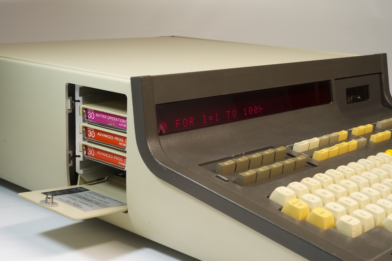
The 5 slots for plug-in cartridge ROMs to extend the firmware.
|

|

View of the cassette tape drive.
|

Rear view with 4 external I/O Slots and printer connector.
No, that's not the original fan filter color.
It's a piece of Scotchbrite which makes a pretty good substitute.
The original filters tend to decay and crumble.
Also missing are the black plastic bumpers on the left and right sides. The screws which should be holding them on are present, but the plastic of the bumpers decays and breaks.
|

Interior view. |

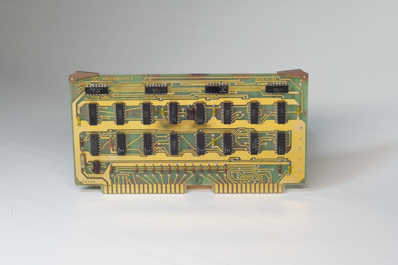
The board assemblies are both uniquely color coded by the extraction handles and uniquely keyed by the size and positioning of the edge connectors.
The color codes are the same as the common resistor code and form the last two-digits of the assembly number,
e.g. the front-most board visible here is assembly 64.
The full assembly number is present in the foil pattern or a label on the board.
|
Assembly 11: CPU I/O Register and Device Flags.
|

Assembly 12: CPU Clock and I/O State Machine.
8 MHz crystal for the master clock. |

Assembly 13: CPU Microcode Engine.
The 7 microcode-store ROMs can be discerned. |

Assembly 14: CPU Registers and ALU
|
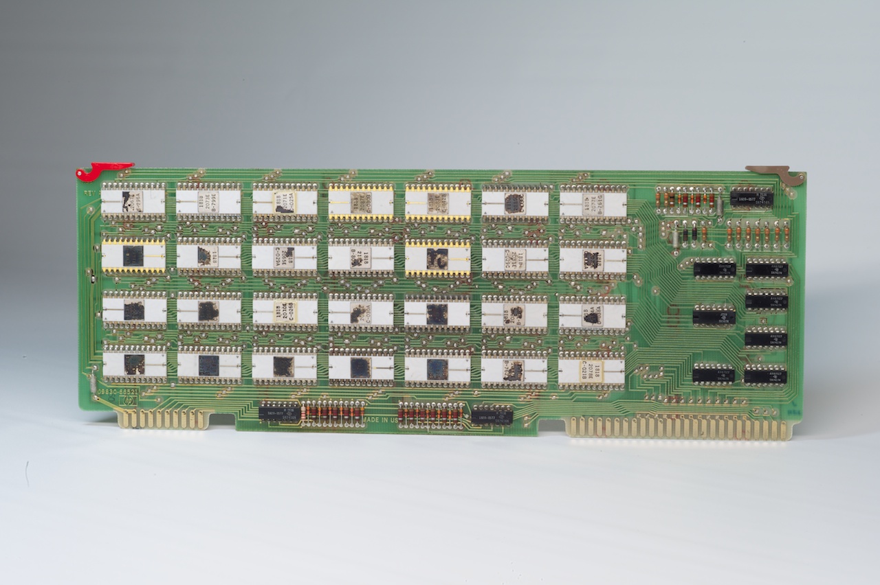
Assembly 21: Basic ROM.
7KW of firmware in twenty-eight 512*8 MOS ROM chips. |

Assembly 25: ROM Buffer.
ROM-bank address decoding and some bufferring for the ROM cards and cartridges. |

Assembly 9830-66526: Basic II ROM Card.
Another 1/2 KW to complete the standard firmware. |

Assembly 11274-66520: String Variables Option ROM Card.
|

Assembly 11272-66520/69520: Extended I/O Option ROM Card.
|

An example of a plug-in Cartridge ROM (11273B).
|

Assembly 02: External I/O Bus and 9866 Printer Interface.
|

Assembly 03: Cartridge ROM bus.
|

Assembly 82: M-Register.
The memory address register, cycle control state machine, and refresh control. Assemblies 82, 83 and 84 constitute the "standard" RAM board-set, replacing assemblies 22, 23 and 24 of the "original" set. The standard set provides 4KW per board, while the original set had 2KW per board. |

Assembly 83: T-Register.
All data transfer between the CPU and memory goes through here. |

Assembly 84: 4KW RAM.
Sixty-four 1K*1 Intel 1103 dynamic RAM chips. |
|

Assembly 92: M-Register for the 9830B.
The 9830B allowed for a full 16KW of RAM with new 8KW memory boards.
The M Register also had to be replaced to support the new memory boards.
|

Assembly 94: 8KW memory board for the 9830B.
The memory chips are TMS4060 4K*1 dynamic RAMs.
|

Assembly 32: Keyboard Logic
|

Assembly 34: Keyboard Interconnect
|

Assembly 41: Display.
Thirty-two 5*7 dot-matrix alphanumeric LED characters, and decoders and drivers. |

Assembly 42: Display Controller. The chip on the upper right is the character generator ROM.
|

Assembly 51: Power Supply
|
|

Assembly 61: Tape Drive Device Interface.
Also contains the beeper device, as evidenced by the little speaker. |

Assembly 62: Tape Drive Control
|

Assembly 63: Tape Drive Read / Write
|

Assembly 64: Tape Drive Motor Control
|
The Tape Transport.
(photo:bh) |

Assembly 65: Tape Interconnect Board, with the transport mounting frame.
(photo:bh) |

The various elements on the transport plug into the interconnect board.
(photo:bh) |
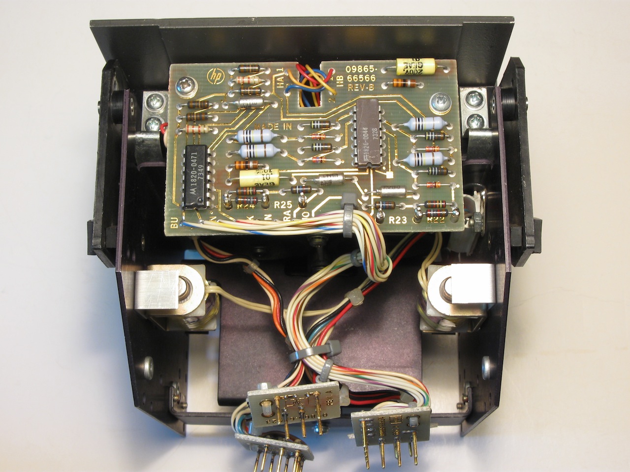
Assembly 66: Tape Head Board mounted on the bottom of the transport.
(photo:bh) |

An example of an original HP tape cassette, the System Test cassette.
|