|
|
Of the 2^5=32 possible states of the function execution state machine, 21 are used. They may be categorised into the following groups, based on the primary action they perform:
Table 1 lists the utilised states and the actions performed during them. A given state may be used in several procedures and more than one action may be performed during that state depending upon which procedure is executing.
| Table 1: Function Execution State Actions | |||
| Group | State | Procedures | Actions |
|---|---|---|---|
| Idle | 0 | - | - |
| Shift Left |
4 | UMAS,SQRT1 | shift Y left, ++X[dp] |
| UMAS | ++DP | ||
| 7 | UADDSUB,UDAS,SQRT2,F54 | shift Y left, ++Y[dp] | |
| UDAS,SQRT2 | ++DP | ||
| UDAS | if nGAM and Y[dp]>=12 or DP=0: 1->BET | ||
| 19 | UADDSUB,UDAS | shift X left, --Y[dp] | |
| UDAS | if C on DGT1: 1->GAM | ||
| 24 | DIV,SQRT1 | shift X left, ++X[dp] | |
| 28 | UDAS | shift M2 left including [dp] | |
| Shift Right |
11 | SQRT1,F54 | shift Y right, --Y[dp] |
| 20 | DIV,UDAS,SQRT1,SQRT2 | shift X right, --X[dp] | |
| SQRT1 | if X[dp]=even after decrement: 1->GAM | ||
| Arithmetic | 9 | UADDSUB,UMAS,UDAS,SQRT1,SQRT2,F54 | YM + X -> YM, 0 -> FNEG |
| F54 | 1 -> BET | ||
| SQRT1 | ++DP | ||
| SQRT2 | cycle DP, when DP=0: 5->B | ||
| 22 | UDAS,SQRT2 | Y - X -> Y, 0 -> BET | |
| SQRT2 | cycle DP, when DP=0: 5->B | ||
| Register Copy |
6 | UDAS,SQRT2 | X -> Y, but [dp] not copied |
| 10 | MUL,DIV | X -> Y | |
| MEMSAVE | X -> M | ||
| 13 | UDAS | M2 -> X | |
| 21 | fin | YM -> X, if nW0: 1->FNEG | |
| Decimal Point Only |
1 | SQRT1 | ++X[dp] |
| 5 | UADDSUB,UMAS,F54 | Y[dp] + X[dp] -> Y[dp] | |
| 14 | UDAS | ++M2[dp] | |
| 25 | UADDSUB | X[dp] + Y[dp] -> X[dp] | |
| 26 | UADDSUB,UDAS | Y[dp] - X[dp] -> Y[dp] | |
| F54 | Y[dp] - KR -> Y[dp], KR -> X[dp] | ||
| Clearing | 16 | ALLCLR | 0 -> X, 0 -> Y |
| CLRENT,SQRT2,F54,fin | 0 -> X | ||
| UDAS | 0 -> M2 | ||
| SQRT1 | 0 -> Y | ||
| MEMGET | 0 -> M | ||
| F54 | if nTRUNC: 5 -> X[2] | ||
| Other | 3 | UMAS | 9 -> X[16] |
| SQRT2 | cycle DP, when DP=1: ++X[DGT] | ||
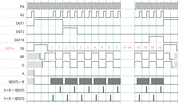
To shift a register left one digit (*10) the A and B latches are loaded alternately with digits from the register, under control of the toggling GR flag, and written back out to the register one digit period later. The GR flag also alternately disables either the A or B latch from being fed to the arithmetic unit so no arithmetic takes place and digit data is fed straight thru, to be written out to core. The Q flag remains constant so only the one register is involved.
There are a few exceptions to this shifting at the beginning of the number cycle. During DGT1 period, the A input to arithmetic is not suppressed, and, as B=0, the DP is rewritten to the same digit, rather than being shifted. Also during DGT1, a carry is injected into the arithmetic unit, thus incrementing the decimal point position, so it keeps up with the new position of the number. At the end of DGT1, A is cleared rather than being carried into DGT2, so the LSD of the number becomes 0.
State 28 disables these exceptions so the decimal point digit value is shifted into the LSD. This is used during division for incrementing and shifting the building quotient.
For shifting right (/10), the DGT counter counts down rather than up, and subtract is enabled to the arithmetic unit for DGT1 so the injected carry is a borrow and decrements the decimal point position.
| Figure 2: Shift State Cycles |

|
The data handling during a number cycle described so far has only dealt with one register or operand. When two registers are involved (as for addition or subtraction), the digits of both registers must be retrieved from core in one digit period. To this end, the digit period is doubled to span two memory cycles (figure 6). Within each digit period the A and the B latches are alternately loaded under control of the GR flag, but, in addition, the Q flag is toggled, resulting in memory cycles affecting digits in, alternately, the X and Y registers (or the X register and a memory register).
The operands of the arithmetic operation may be swapped ( X±Y->X versus Y±X->Y ) by changing the state in which the Q flag starts at the beginning of the number cycle.
Note that while B is only cleared once during a double digit period, A is actually being cleared twice during this period, so that when B is rewritten to core (to restore data cleared during the core memory destructve read cycle) it is just B (0+B=B).
| Figure 3: Arithmetic State Cycles |

|
To copy one register to another, a similar procedure to that of arithmetic is used. A double-digit state cycle is established, but the loading of the A latch from core is suppressed and so remains 0. Consequently the contents of the B latch alone is written out.
| Figure 4: Register Copy State Cycles |

|
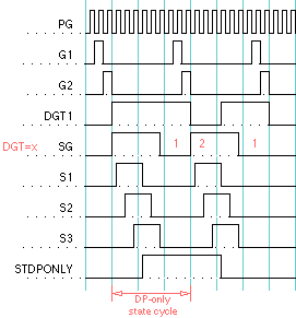
| Figure 5: DP-Only State Cycles | |

|
Note the DGT counter is always reset during a state-clock cycle so the next number cycle always starts at digit 1.
|
Architecture |
Electronics |
Arithmetic |
Timing |
T States |
States |
Procedures |
Numeral-Entry
Casio AL-1000 Technical Description EEC |
bhilpert Nov 2004 |